| Availability | In Stock |
|---|---|
| Condition | Brand New |
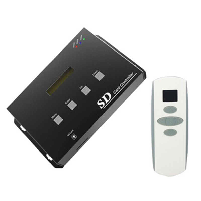
The SD card SPI controller uses an advanced computer control chip to control various lamps with LED as light sources, such as point light source, soft light bar, wall washer, glass curtain wall lamp, etc. Using key control, it has the functions of selecting pattern file, adjusting change rate, output IC selection, date setting display, holiday timing, power-off storage and switch. The system powers on and searches for all "*.LED" files in the SD card and sorts them by file name from small to large, and reads and plays the last saved file mode. The user can press the button to select the changing pattern. After selecting all the files, press the Select File Add button again to display the pattern file in a loop. It has the advantages of flexible wiring, convenient wiring, and simple use; according to the actual needs of customers, it can achieve four-channel and flat jump, gradient, strobe, horse racing, running water, running text, pictures, video and other lighting changes. The user can also edit the data pattern file through the attached pattern editing software (LedEditor v1.0). There are many different patterns and it is easy to use. For the detailed editing method, please refer to the manual of the editing software.


Technical Parameters
●Working Temperature: -20-60℃
● Power Supply Voltage: DC12-24V
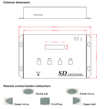
● Dimensions: L240 *W145 *H39 mm
● Packing Size: L280 *W185 *H75 mm
● Net Weight: 894g
● Gross Weight: 1250g
●Power Consumption: <1W
● Frame Frequency: The fewer points used per channel, the larger the maximum adjustable frame number, and vice versa. The recommended number of frames is 20~30fps.
● Support Chips: conventional single-wire and two-wire ICs in the market
● Output: 4 SPI signals
● Control Points: related to the frame rate, the slower the frame rate, the more points can be set, and vice versa. When testing at 30fps, each channel can be set up to 432 points, and the total number of points of the four channels can reach 1728 points. For details, please refer to Table 3.
● Grey Level: 32~255 levels (varies according to the driver chip)
● Maximum Number of Pattern Files: 64
Specifications Download 
Interface description
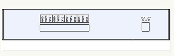
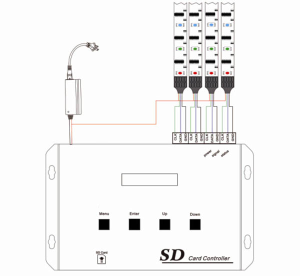
SPI signal output interface: GND is public ground, DATA data interface, CLK clock interface. Power port: input DC voltage 5-24V.
SD card slot

Power: Power indicator, power on light.
sigmal: Buttons and remote control indicator lights, there are button operation or remote control operation indicator flashes.
Status: working status indicator, the indicator flashes when there is SPI output, the flashing frequency is related to the output speed
Built-in mode:
|
Mode |
Mode Description |
Mode |
Mode Description |
|
0 |
Static black |
18 |
Red reverse tail |
|
1 |
Static red |
19 |
Green positive tail |
|
2 |
Static green |
20 |
Green reverse tail |
|
3 |
Static blue |
21 |
Blue positive tail |
|
4 |
Static yellow |
22 |
Blue reverse tail |
|
5 |
Static purple |
23 |
Seven-color forward running tail |
|
6 |
Static cyan |
24 |
Seven-color forward running tail |
|
7 |
Static white |
25 |
Positive purple-red-purple gradient transition |
|
8 |
Red right horse race |
26 |
Positive yellow-green-yellow gradient transition |
|
9 |
Green right horse race |
27 |
Positive cyan-green-cyan gradual transition |
|
10 |
Blue right horse race |
28 |
Positive purple-blue-purple gradient transition |
|
11 |
Three primary colors strobe |
29 |
Positive cyan-blue-cyan gradient transition |
|
12 |
Seven-color strobe |
30 |
Positive white-red-white gradient transition |
|
13 |
Three primary colors jump |
31 |
Positive yellow-red-yellow gradient transition |
|
14 |
Seven colors jump |
32 |
Red-yellow-red gradient |
|
15 |
Three-color three-way overlap running forward |
33 |
Green-cyan-green gradient |
|
16 |
Forward seven colors |
34 |
Blue-purple-blue gradient |
|
17 |
Red positive tail |
|
|
Support light bar
|
Numbering |
Model |
Signal line |
|
1 |
TM1803 |
DATA |
|
2 |
TM1809 |
DATA |
|
3 |
TM1812 |
DATA |
|
4 |
UCS1903 |
DATA |
|
5 |
UCS2903B |
DATA |
|
6 |
WS2811 |
DATA |
|
7 |
LPD6803 |
DATA, CLK |
|
8 |
WS2801 |
DATA, CLK |
|
9 |
TLS3001 |
DATA |
|
10 |
TLS3008 |
DATA |
|
11 |
P9813 |
DATA, CLK |
|
12 |
LPD8806 |
DATA, CLK |
Frame rate and number of LED files
|
Speed |
Maximum points per channel |
Four points total |
|
12fps> |
1024 |
4096 |
|
15fps |
850 |
3400 |
|
20fps |
600 |
2400 |
|
25fps |
512 |
2048 |
|
30fps |
432 |
1728 |
|
35fps |
372 |
1488 |
|
40fps |
325 |
1300 |
Note: The maximum number of points corresponding to the frame rate here refers to the points of the general pattern (the.led file is not large). If the pattern is too complicated (the.led file is too large), you must reconsider the point problem. Do you need to reduce the number of points to prevent the speed of the configuration? The controller can't handle it and die.
1. The single-line IC is shown in the figure. The signal line can only be connected to the terminal corresponding to the data:
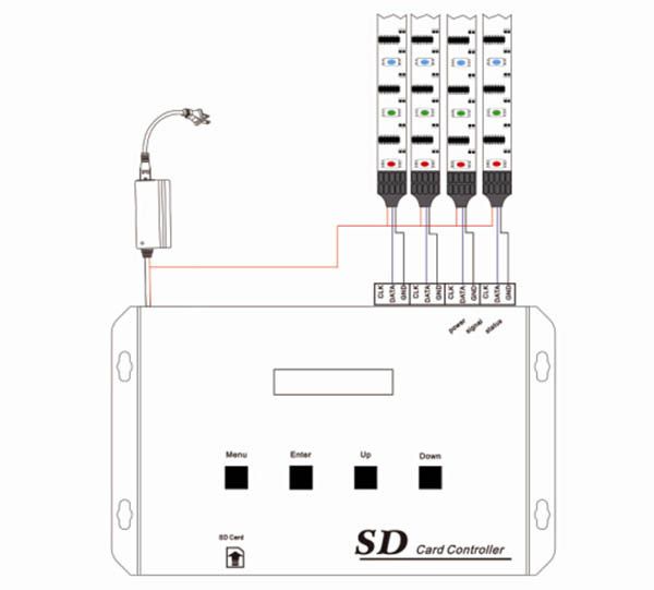
2. The two-wire IC is shown in the figure: the clock line and the data line are connected to the corresponding terminals: