| Availability | In Stock |
|---|---|
| Condition | Brand New |
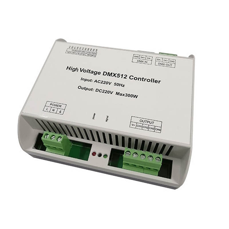
The DMX universal controller uses an advanced computer control chip to receive the DMX-512 standard digital control signal widely used in the world and convert it into a PWM control signal to drive the LED; it can be connected to the DMX digital console to achieve dimming or various program changes.


Technical Parameters
Working Temperature: -20-60℃
Power Input: AC200 to 265V
Output: DC220V 1.3A Pmax=300W
Connection Method: Common anode
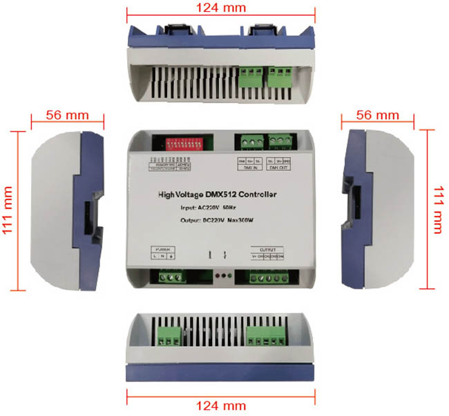
Dimensions: L124*W111*H56 mm
Packing Size: L135*W135*H60 mm
Net Weight: 286.7g
Gross Weight: 400g
Output Current: <1.3A (4 channels total current)
Output Power: 300W, with short circuit protection
Controller Output Frequency: 980HZ
Specifications Download 
Dimension
Interface description
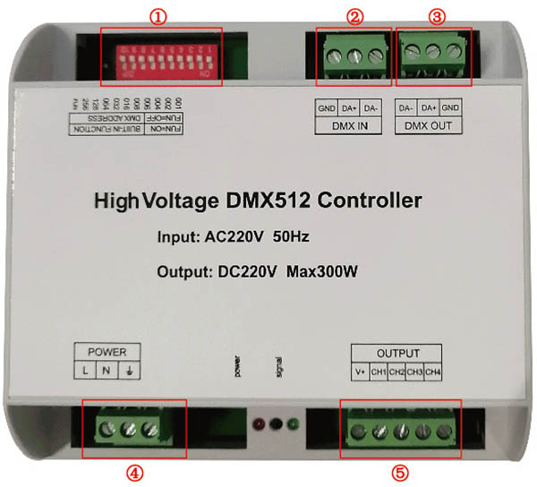
①: address code and function setting; ②, ③: DMX input and output interface; ④: power interface; ⑤: load interface
Instructions for use
DMX address code setting
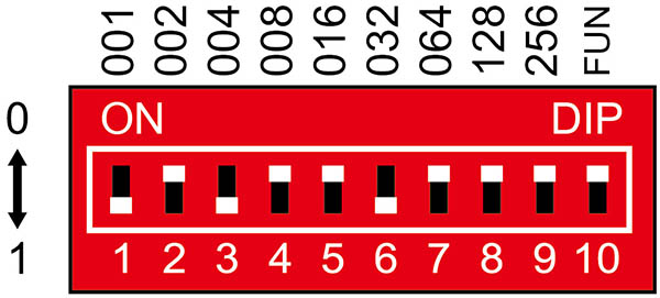
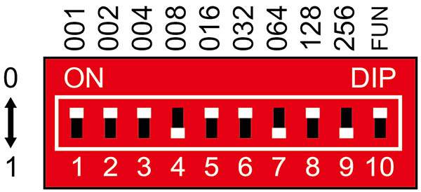
Each DMX universal controller occupies 4 DMX addresses. The address is set by a coding switch. The 1-9 bits of the coding switch is binary numeric coding switches that set the DMX start address code. The first bit is the lowest bid and the 9th bit is the highest bit., A total of 511 address codes can be set. DMX start address code = the sum of the bit values of the coding switch 1-9 bits, dial the coding switch backwards (ON is set to 1), the bit value can be obtained; dial the coding switch forward (set to 0), then the bit Has a bit value of 0.
Code switch FUN (10) = OFF (set to 0) can accept DMX signal function
Example 1: As shown in Figure 1, set the DMX to start address code to 37, and set the 6th, 3rd, and 1st positions of the coding switch to 1, and the remaining positions to 0. At this time, the total value of the 1-9 bits of the coding switch is 32 +4+1 is the DMX512 start address code 37.
Example 2: As shown in Figure 2, the DMX start address code is set to 328, then 9th, 7th, and 4th positions of the coding switch are set to 1, and the remaining positions are 0. At this time, the total value of the 1-9 bits of the coding switch is 256+64+8 is the DMX start address code 328.
Instructions for other functions
Test function:
The 10th digit of the DIP switch is FUN, which is a built-in function key. When FUN=OFF, it is the DMX decoder function and accepts DMX signals.
The test function when FUN=ON is shown in the figure:
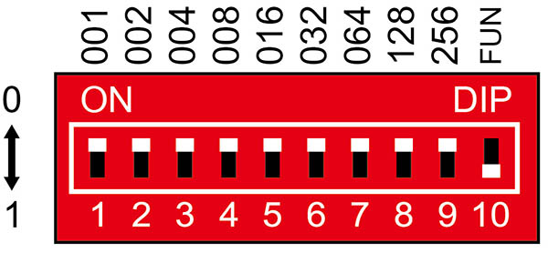
1-9 switch OFF: black
Switch 1=ON: CH1 is on
Switch 2=ON: CH2 is on
Switch 3=ON: CH3 is on
Switch 4=ON: CH4 is on
Switch 5 = ON: all 4 channels are on
Switch 6=ON: 4-channel average strobe (6-speed selection)
Switch 7 = ON: four-colour jump back and forth (6-speed selection)
Switch 8=ON: four-way back-and-forth increasing and decreasing jump (6-speed selection)
Switch 9=ON: Four-color gradient (6-speed selection)
Dynamic effect speed selection
When testing the function, switch 6=ON is a 4-channel average strobe effect, switch 7=ON is a four-colour back and forth transition effect, switch 8=ON is a four-way back and forth increasing and decreasing transition effect, switch 9=ON is a four Color gradient effect, each effect has 6-speed options:
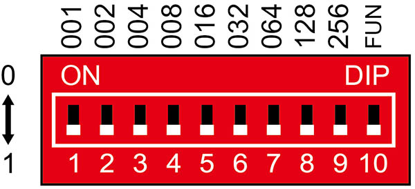
1-5 switch = OFF: 0 speed
Switch 1 = ON: 1 speed
Switch 2=ON: 2nd speed
Switch 3 = ON: 3 speeds
Switch 4=ON: 4 speeds
Switch 5=ON: 5 speeds (fastest speed)
When multiple switches are ON at the same time, the switch with the larger value shall prevail. As shown in Fig. 4, when all DIP switches = ON, the decoder speed at this time: the mode speed is 5 gears.
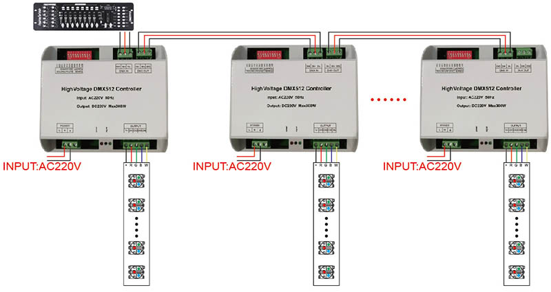
Typical application