| Availability | In Stock |
|---|---|
| Condition | Brand New |
LYC500 is a high-performance wireless charger product independently developed by our company, which is suitable for providing contactless charging for various mobile robots or devices (such as AGV, AGC, RGV, electric forklifts, golf carts, and hotel service robots, etc.), It can realize the complete automation of the battery charging process, convenient to use and simple to maintain. The use of adaptive control technology overcomes the impact of charging distance and load changes on system performance. It has high control accuracy and can provide accurate and reliable charging for lithium batteries, lead-acid batteries, nickel-metal hydride batteries and supercapacitors, protecting and extending battery life.
The output power of LYC500 is 300W, the wireless transmission efficiency is better than 85%, the electromagnetic radiation intensity "Electromagnetic Environment Control Limit (GB 8702-2014)" requirements, safe, green and energy-saving. The key components in this product are all imported components and have undergone rigorous testing of the whole machine to ensure long-term stable operation.
Features
1. Non-contact charging, high efficiency, long life, can realize fragmentation of charging time;
2. Original magnetic core structure design, low magnetic leakage and low radiation;
3. The original multi-loop resonance design, low loss, transmission frequency bandwidth;
4. The original multi-loop adaptive control algorithm ensures that the system is always in the best working state;
5. Independently developed 2.4GHz frequency hopping communication algorithm, with low data transmission delay and strong anti-interference ability;
6. Self-developed distance sensing and position confirmation algorithms to effectively prevent charging misoperation;
7. Multiple overload protection design to ensure stable and reliable equipment operation;
8. The integrated structure of the transformer and control circuit, saving space and convenient installation;
Technical Parameters
Input voltage: AC220V±15%, single phase 50Hz
Input current: 4A (maximum)
Output voltage: 12.0V to 30.0V (adjustable, factory setting 28.8V)
Output current: 7 to 15A (adjustable, factory setting 10A)
Voltage regulation accuracy: ±0.3%
Steady flow accuracy: ±1.0%
Voltage ripple: ≤0.3%
Power efficiency: ≥85%
Charging distance: air gap length: 20±10mm
X-axis deviation: ±20mm
Y-axis deviation: ±20mm
Charging frequency: 30 to 60kHz (self-adjusting)
Data transmission: working frequency band: 2.400 to 2.485GHz
Spread spectrum method: AFH
Transmit power: 0dBm
Ambient temperature: -20 to +50℃
Storage temperature: -30 to +60℃
Insulation resistance: ≥100MΩ
Withstand voltage: AC1750V (1min)
Shock resistance: 10G (omnidirectional)
Vibration resistance: 19.6m/sec2 (10 to 55Hz)
Dimensions: 170(W) * 150(H) * 52(D)mm
Weight: 5.0kg
Features
LYC-500T power terminal indication function:
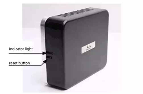
(1) After normal power-on or pressing the reset button, the red indicator light often turns "on" for 1 second and enters the standby state, and the red indicator light enters the slow flashing state;
(2) When the power receiving terminal is in place and the communication is normal, the coupling degree detection phase is performed, and the blue indicator light enters the normally "on" state;
(3) After the coupling degree test passes, the blue indicator light enters a fast flashing state, indicating that it has entered the normal charging state;
(4) After charging, the indicator light on the power supply is in the standby state, and the red indicator light enters the slow flashing state;
LYC-500R power receiving terminal indication function: (Take the robot as an example: the power receiving terminal is on the robot)
(1) After the battery is normally connected or the reset button is pressed, the red indicator light often turns "on" for 1 second, and enters the standby state, the indicator does not indicate that it is often "off" state;
(2) When the power receiving terminal reaches the charging position, the robot gives a charging signal (active high), and the green indicator light enters a slow flashing state;
(3) After normal charging, the green indicator light on the receiving end flashes quickly;
(4) If the power receiving end is locked due to a fault or the position is not correct, the red indicator light on the power receiving end enters a fast flashing state;
(5) After charging is completed, the indicator light on the power receiving end is off.
Method of operation
Power on operation
(1) After the wiring harness is correctly connected, connect the power plug at the power end to the single-phase 220V power socket. The specific wiring diagram is shown in Figure 1;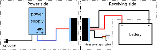
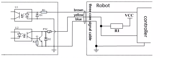
Note: Brown is the start control line, high level is effective, the input voltage is 3 to 30VDC;
Yellow is the fault indication line, low level is effective, OC output, maximum sink current 200mA, withstand voltage 30VDC;
Blue is the signal ground.
Figure 1 is a schematic diagram of the reference wiring. When the robot is in place to charge, the controller directly outputs a high level (voltage 3-30VDC) signal to the brown line to start charging; when it is necessary to stop charging, the controller directly outputs a low level signal to Stop charging on the brown wire.
The fault signal wiring is shown in Figure 2. It is connected to VCC through a pull-up resistor R1 (note whether the internal level of the controller is consistent with the VCC voltage). The value of resistor R1 is related to the size of VCC (maximum sink current 200mA, withstand voltage 30VDC)). Under normal circumstances, the yellow fault indication line shows a high level state. When there is a fault or the position is not accurate, the yellow fault indication line shows a low level state. The charger is in a locked state and can be unlocked by resetting the start signal Dead state. (2) The power indicator is as described in "LYC-500T Power End Indication Function";
(3) After the power receiving end is connected to the battery, the power indicator is as described in "LYC-500R power receiving end indication function".
Installation method
1. Equipment Composition
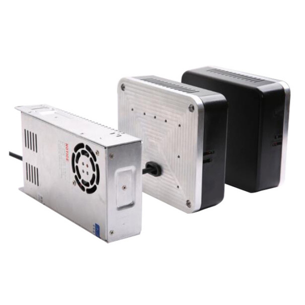
The equipment consists of three parts in total:
(1) Power converter;
(2) Wireless transmitter;
(3) Wireless receiver.
2. Installation
(1) The power terminals (power converter and wireless transmitter) of the LYC500 charger are fixed in the charging area;
(2) The power receiving end (wireless receiver) of the LYC500 charger is fixed on the robot;
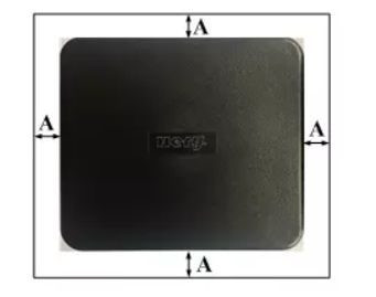
(3) There is no metal within 2cm around the wireless transmitter of LYC500 power receiving end and power supply end, as shown in Figure 3 below, A≥2cm.
Physical connection
1. Physical wiring diagram of power converter
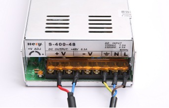
The brown-blue-yellow three-core wire is directly connected to the AC220V power socket, and the red-blue two-core wire is connected to the wireless transmitter. The specific physical wiring diagram is shown in Figure 4 below.
2. Physical wiring diagram of the receiving end
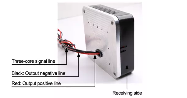
The following figure is the physical wiring diagram of the power receiving end. The output positive wire (red) is directly connected to the battery positive electrode, the output negative wire (black) is directly connected to the battery negative electrode, and the signal wire is connected to the robot control system
Common faults and troubleshooting
1. LYC-500T power terminal fault and troubleshooting
(1) After the robot gives the charging signal, the green indicator light "off" and the red indicator light "on" appear during the coupling degree detection stage, it may be that the coupling degree detection fails, first check the device distance and offset, if If it is not within the range, you need to readjust the position; if it is within the range, wait for one minute, the system will automatically re-recognize, if there is still a green indicator light "off", a red indicator light "on" occurs, then the power Run after all electrical terminals are reset.
(2) If the red indicator light on the power supply side is always in the "bright" state or the green indicator light is in the "bright" state, or the red and green indicators are always in the "bright" state, press the reset button to reset.
(3) If the indicators on the power supply end are always in the "off" state, press the reset button to reset and indicate that the red light does not indicate, then check whether the single-phase 220V input is normal, and if it is normal, then check the wiring for virtual connections.
(4) If the power supply end is close to the power receiving end, the robot gives a charging signal, the power receiving end indicates that the green light has entered a normal flashing state, and the power end indicates that the red light is still in a slow flashing state, then connect the power supply end and the power receiving end Run after resetting.
2. LYC-500R receiving terminal failure and troubleshooting