

| Availability | In Stock |
|---|---|
| Condition | Brand New |
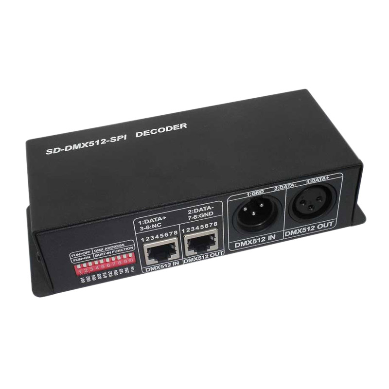
SD card DMX signal decoder is one of our company's standard products. The SD card stores the edited pattern file and outputs it as SPI signal. It can be controlled by the DMX console or other DMX control equipment, and the files and speed to be played can also be selected through the dial switch. It can complete the effects of jumping, gradual change, horse racing, running water, chasing, strobe and so on. The user can edit the data pattern file through the attached pattern editing software (LedEditorv1.0). There are many different patterns and it is easy to use. For the specific editing method, please refer to the manual of the editing software.


Technical Parameters
● Working Temperature: -20-60℃
● Power Supply Voltage: DC12V
● Support Maximum Pixel: 1024
● Output: SPI
● Maximum Number of Files: 62
● Dimensions: L224ΧW128ΧH37 mm
● Packing Size: L230ΧW180ΧH55 mm
● Net Weight: 320g
● Gross Weight: 430g
● Static Power Consumption: <1W
Specifications Download 
External Dimension

Interface description
Power input, SPI signal output and SD card interface:

DMX input and output interface: card faucet interface

DMX input and output interface: RJ45 interface

Address code and function setting interface:

Instructions for use
The controller has two control methods: dial code control and DMX control. When the last dial switch (FUN) is pressed, it is the dial control mode, otherwise it is the DMX control mode.
1. Dip switch control
When the last DIP switch is turned down, it is the DIP control mode. In this mode: the first 6 DIP switches (1~6) select the sequence number of the file to be played, and up to 62 files can be selected. When the values of these 6 switches are selected When adding 1 to the number of valid LED files in the SD card, all files are played in a loop. The DIP switches No. 7, 8, and 9 are for speed selection and will be divided into 8-speed gears according to their values. When none of the three dial codes is pressed, the playback speed is the initial set speed of the file.
2. DMX control method
The channel corresponding to the DMX address code of the controller is the file selection channel, and the channel corresponding to the address code +1 is the speed control channel. For example address code is 1, the sample selection channel is CH1, speed control channel is CH2, DMX channel value (0~255) The greater the channel value, the faster the speed.
Note: Each DMX module occupies 2 channels, and the ID value of the DMX module should be edited according to the rules of 1, 3, 5, 7, 9.
DMX address code setting
Each DMX universal controller occupies 2 DMX addresses. The address is set by a coding switch. The 1-9 bits of the coding switch is binary numeric coding switches that set the DMX start address code. The first bit is the lowest bid and the 9th bit is the highest bit. , A total of 511 address codes can be set. DMX start address code = the sum of the bit values of the coding switch 1-9 bits, turn the coding switch down (ON set to 1), you can get the bit value; the coding switch up (set to 0), then the bit value is 0. Code switch FUN (10) = OFF (set to 0) can accept DMX signal function
1), Example 1:
As shown in Figure 1, set the DMX start address code to 37, set the 6th, 3rd, and 1st positions of the coding switch to 1, and the remaining positions to 0. At this time, the coding switch
The sum of the bit values of 1-9 bits is 32+4+1, which is the DMX512 start address code 37.

2), Example 2:
As shown in the figure, the DMX start address code is set to 328, then 9th, 7th, and 4th positions of the coding switch are set to 1, and the remaining positions are 0. At this time, the total value of the 1-9 bits of the coding switch is 256+64+ 8, which is the DMX start address code 328.

