

| Availability | In Stock |
|---|---|
| Condition | Brand New |
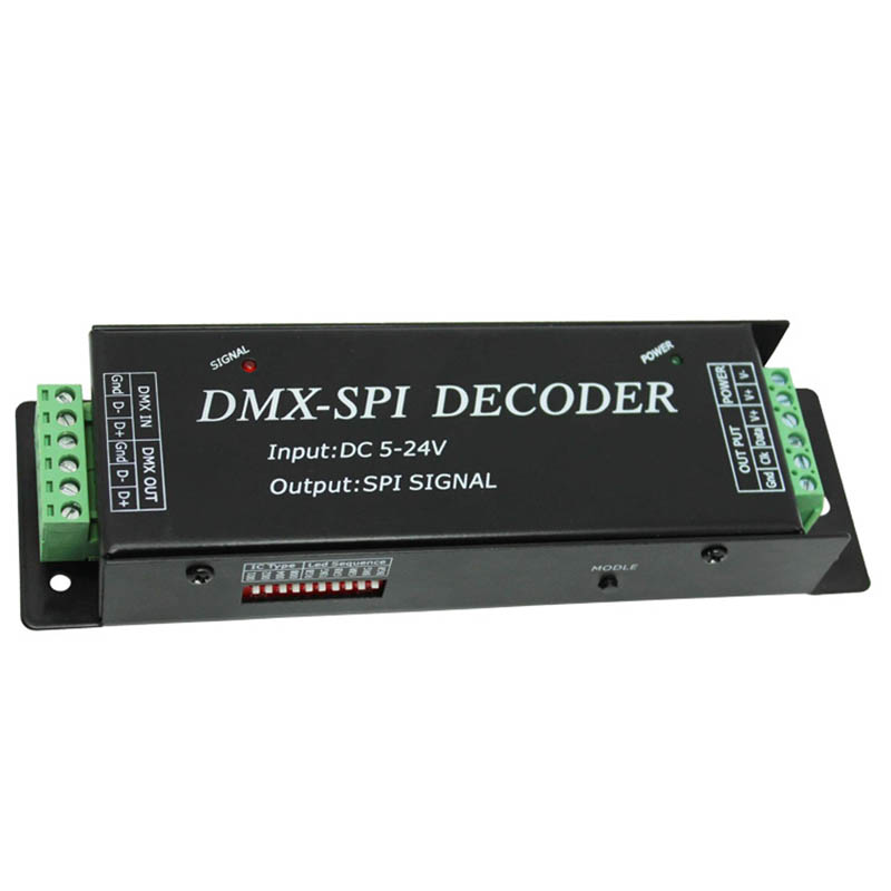
This DMX-SPI decoder adopts an advanced computer control chip, receives DMX-512 standard digital control signals widely used in the world, and converts it into SPI controller signals to drive LED light bars. It can support 10 different types of light bars and DMX signal ports at the same time. It has lightning protection measures; it can be connected to the DMX digital console to achieve dimming or various program changes; when the DMX console is not connected, 35 default patterns are built-in, which can be selected by the MODEL key, and the default number of points is 512.


Technical Parameters
Working Temperature: -20-60℃
Power Input: DC 5V-24V
Output: SPI signal (DATA, CLK)
Dimensions: L175*W53*H27 (mm)
Packing Size: L180*W58*H55 (mm)
Net Weight: 256.5 g
Gross Weight: 350g
Maximum Output Power: 480W
Specifications Download 
Dimension

Interface description
The DMX signal terminal adopts 6PIN green terminal interface, and the wiring method is as follows:

DMX IN: DMX signal input interface, D+ connects the signal positive, D- connects the signal negative, Gnd ground wire.
DMX OUT: DMX signal output interface, D+ connects the signal positive, D- connects the signal negative, Gnd ground wire.
The 6Pin green binding post interface is used for the power supply and load output terminals. The wiring method is as follows:

POWER: Power input interface, V+ is connected to the positive pole of the power supply, V- is connected to the negative pole of the power supply, and the power supply voltage range is DC5-24V.
Instructions for use
1. Decoder parameter setting
The type of light bar supported by the decoder can be modified through the side dial switch. This decoder supports 10 different IC light bars on the market,
The following table:
| Numbering | Mode | Signal Line |
| 1 | LPD6803 | DATA, CLK |
| 2 | TM1803 | DATA |
| 3 | TM1809 | DATA |
| 4 | TM1812 | DATA |
| 5 | UCS1903 | DATA |
| 6 | WS2811 | DATA |
| 7 | WS2801 | DATA, CLK |
| 8 | TLS3001 | DATA |
| 9 | TLS3008 | DATA |
| 10 | P9813 | DATA, CLK |
If the light bar has two signal wires, you need to connect the ground wire, clock wire, and data wire to the controller GND, CLK, and DATA; if it is a signal wire light bar, connect its ground wire, data wire, and controller Connect GND and DATA.
Note: If the voltage of the V+ terminal of the light bar is the same as the input voltage of the controller, you can directly connect it to the controller V+; if not, you need to connect another power supply.
The RGB order of the light bars may also be different, because many light bars on the market have different specifications, some are red, green and blue, and some are red, blue, green, red, blue, etc. Therefore, the side dial switch provides RGB line order Modifications.
The dial code on the side is shown below:

IC Type: Light bar model selection. The cumulative sum of the first 4 dialing codes in the above figure is 1*1+2*0+4*0+8*0=1. Looking up the table shows that it is LPD6803.
Led Sequence: RGB sequence selection. The dial code 5 in the above picture is pressed, indicating that the color sequence of the light bar is RGB.
Note: When the cumulative sum of IC Type is greater than 10, such as 12, 14, the default is 10, which is P9813; when the Led Sequence has two or more dial codes pressed, such as 5, 7, 9 The default value is 9 by default, which is BRG.
2. Instruction description: The red power indicator light is always on when the power is connected, the green signal light is on when the button is pressed, and it is always on when the DMX is connected.
3. When there is no DMX signal connection, press the MODEL button to switch the mode. When the DMX is connected, it is only controlled by the DMX, and the button is invalid.
The mode changes are as follows:
|
Mode |
Mode Description |
Mode |
Mode Description |
|
1 |
Static red |
19 |
Green positive tail |
|
2 |
Static green |
20 |
Green reverse tail |
|
3 |
Static blue |
21 |
Blue positive tail |
|
4 |
Static yellow |
22 |
Blue tail |
|
5 |
Static purple |
23 |
Seven colors running backward |
|
6 |
Static cyan |
24 |
Seven-color forward running tail |
|
7 |
Static white |
25 |
Positive purple-red-purple gradient transition |
|
8 |
Red right horse race |
26 |
Positive yellow-green-yellow gradient transition |
|
9 |
Green right horse race |
27 |
Positive cyan-green-cyan gradual transition |
|
10 |
Blue right horse race |
28 |
Positive purple-blue-purple gradient transition |
|
11 |
Three primary colors strobe |
29 |
Positive cyan-blue-cyan gradient transition |
|
12 |
Seven-color strobe |
30 |
Positive white-red-white gradient transition |
|
13 |
Three primary colors jump |
31 |
Positive yellow-red-yellow gradient transition |
|
14 |
Seven colors jump |
32 |
Red-yellow-red gradient |
|
15 |
Three-color three-way overlap running forward |
33 |
Green-cyan-green gradient |
|
16 |
Forward seven colors |
34 |
Blue-purple-blue gradient |
|
17 |
Red positive tail |
35 |
Autoplay 8~34 |
|
18 |
Red reverse tail |
|
|
Typical application
Single power supply connected to a single signal line light bar: applicable when the light bar power supply voltage is the same as the controller power supply voltage and the light bar signal is a single signal line

Single power supply connected to dual signal line light bar: applicable to the same power supply voltage of the light bar and the controller and the light bar is a dual signal line
