

| Select Input Voltage: | 110V±20% (US, CA) (Base), 220V±20% (EU, UK, AU) (Base) |
|---|---|
| Select Kit: | Panel Light + Power Adapter (Base) |
| Select Plug Type: | US (Base), UK (Base), EU (Base), AU (Base) |
| Select Power: | 256 Watts (Base), 320 Watts, 128 Watts |
| Wavelength: | 395-405nm, 365nm-370nm (Base) |
| Availability | In Stock |
| Condition | Brand New |
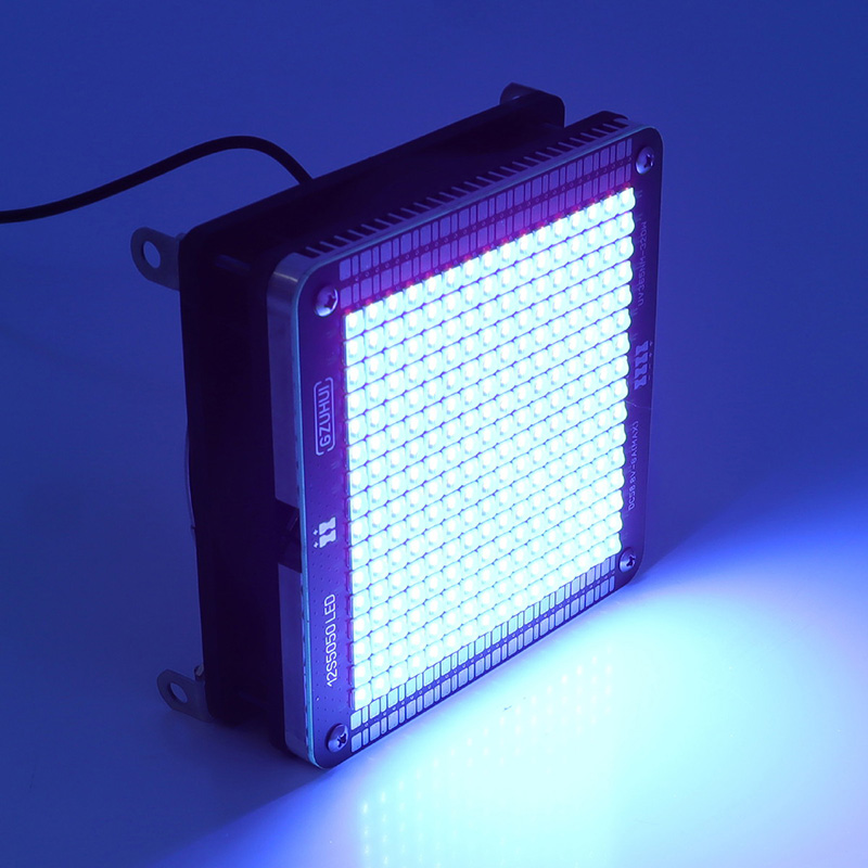
This high power UV-A LED square panel light with 365nm light source is configured with aluminium alloy heat sink, back copper layer and cooling fan inside, which helps dissipate heat better than other ultraviolet light panel. Featuring small size for handheld operation, our 256W high power LED panel has 365nm black light luminous uniformity and allows you to process glue UV curing easily and quickly. No need to preheat, this UV curing light doesn’t produce ozone and is harmless to the human body, usually used for fluorescence response detection, glue and resin curing, UV printing, UV curing machine and medical inspection field. It can be also applied to blacklight party if you like. This low voltage 365nm panel is not waterproof, if you need to put it outdoors, you can add a waterproof shell outside.
For curing, it is recommended to select 365 nanometers.
Before connecting to the power source, please verify that the voltage on the panel matches your local line voltage. A toggle switch on the side of the light panel allows you to switch the voltage to either 110V or 220V.
Regarding Brightness Adjustment:
1. The power adapter we provide has an internal potentiometer for output calibration. This feature allows you to control the brightness of the UV light by adjusting the output current. To use this function, you must open the power adapter’s housing and make adjustments while the unit is powered on (this procedure is technical in nature and is not recommended for frequent use or by inexperienced users).
2. You can use a standard PWM dimmer to adjust the UV brightness. The PWM dimmer must be purchased separately. The electrical specifications for the PWM dimmer are: operating voltage ≥ 60V DC, operating current ≥ 5 A (per light assembly).
At an ambient temperature of 25°C, approximately 58V is required to initiate full-power drive. Once in operation, the full-power drive voltage ranges from 55 to 57V. This is because as the LED temperature rises, its internal resistance decreases linearly. Therefore, our included power adapter features a maximum output current limit to ensure the lamp board’s maximum continuous operating current does not exceed its maximum drive current. This serves as an overheat protection mechanism by controlling the maximum drive current. The light board is sensitive to maximum current; exceeding the current limit poses a direct risk of burning out the light board. If the operating current is uncertain, try starting at 54V and gradually adjusting up to 57V to test for a stable, optimal operating state.
The driver should not exceed the lamp’s rated power; normal operation is guaranteed at this rated power. Exceeding this power rating may accelerate light decay or cause overheating that could burn out the LED chips.
In large-scale matrix light array applications, having too many power adapters can indeed be a hassle. You can specify the required quantity based on your project needs when placing an order. For example, if the installation requires 6 light arrays, we will calculate and provide a single power adapter rated at 6 × 6 = 36A or less. This way, you only need to control this single power adapter to manage the operational status of the entire matrix light array.
Issue of 256W light board burning out when directly driven by a 58V constant-voltage power supply:
When driven directly at the maximum voltage with a constant-voltage supply and without any current-limiting measures, the LED board’s operating current ranges between 6A and 12A within 5 seconds. After startup, as the temperature rises, the LED board’s internal resistance decreases, but the voltage remains stable. Since heat cannot be dissipated efficiently, the temperature continues to rise. The power supply provides a higher current based on the LED board’s internal resistance, causing the current to continuously increase until the LED board burns out due to overheating.
When using a constant-voltage drive, it is recommended to monitor the continuous drive current to ensure it does not exceed the LED panel’s rated current: 256W LED panels should not exceed 4.8A, and 320W LED panels should not exceed 6A.
Why is the 320W lamp rated at a 58V operating voltage and a maximum current of 6A?
This is to meet an expected operating condition, where, during normal use, we want the lamp to enter a fully operational state immediately upon startup and remain stable at a consistent level. This condition is particularly useful for curing time control. 58V is the maximum voltage during a cold start, and 6A is the maximum operating current (this current must not be exceeded, otherwise it will affect the rated lifespan).
The accompanying power adapter is designed to maintain the maximum set current continuously after startup (once the lamp reaches a stable operating state, the voltage drops gradually in response to the lamp’s internal resistance to prevent overheating and burnout).
Constant-voltage operation requires monitoring the current to achieve an ideal stable state, which is determined by the cooling environment and the sustained operating current; if the current exceeds the limit, the supply voltage is reduced to balance the lamp’s operating temperature and current.
A constant 57V power supply allows the 320W light panel to operate continuously:
57V is approximately 70% of the full-power startup voltage for the 320W light module. At this voltage, the light board’s operating current is about 3.5A at startup. As the light board’s temperature rises, its internal resistance decreases, at an ambient temperature of 25°C, the current gradually rises from 4A to around 5A. Under fixed cooling conditions provided by the cooling fan, the ambient temperature and cooling conditions stabilize the LED module’s internal resistance, allowing for stable, continuous operation. In this constant-voltage drive mode, the maximum drive power of the light board is determined by the operating temperature of the LED module. As long as it is not subjected to sustained high temperatures, it can operate continuously and stably.
It is necessary to measure the continuous operating current to assess the LED module’s operating status (a current of 6A represents 100% drive power); of course, maintaining the LED board at 70% power ensures a more stable lifespan.
At what level of light decay can the target equipment continue to function normally? Should the lamp be replaced when light decay reaches 50%, 40%, or 30%?
When light decay reaches this level, the lamp does not go out; it continues to emit light normally. Due to the characteristics of semiconductors, their internal resistance increases after periodic aging, requiring a higher initial voltage to restore the original light intensity. After increasing the voltage, the original light intensity can be restored. Once light decay reaches 60% through stepwise adjustments, it may be necessary to consider replacing the lamp; this issue is inherent to all light sources.
In the practical application of UV light sources, it is necessary to periodically measure light intensity using a UV power meter. When light intensity decreases, the irradiation time must be increased to ensure the target object receives the required amount of light energy (in joules). Based on practical experience, a new light source must be replaced when the light intensity-to-time efficiency becomes unacceptable.
Under stable power supply conditions (without overcurrent) and a stable ambient temperature of 25°C, the ideal light decay after 2,000 hours of continuous operation should be within 40%. This data is based on parameters under full-power drive. If driven at 70% of full power for 2,000 hours, the expected light decay is within 30%. If driven at 60% of full power for 2,000 hours, the expected light decay is within 25%.
If significant light decay occurs within a short period of time, we need to determine whether it is caused by the light fixture operating continuously at excessively high temperatures over an extended period. If heat dissipation conditions were more ideal, the fixture’s theoretical service life would certainly be longer, and light decay would be more stable. Burnout can result from unstable power supply or overheating; of course, it may also be caused by high pressure during transportation, which reduces the contact area between the circuit board and the heat sink, leading to failure (this issue has been resolved through ongoing upgrades).


| Product Type: | 365nm UV-A LED Square Panel Light |
| Input Voltage: | DC58.8V |
| Power: | 5A 256W Max |
| UV Wavelength: | 365nm (peak wavelength 365nm, half-wave width 15nm) |
| LED Quantity: | 256 LEDs (16*16 array) |
| Dimensions: | L120mm*W120mm*H52mm(4.7in*4.7in*2in) |
| Current: | 5A |
| Luminous brightness: | Single LED 1W power consumption/ 0.54mw light power per led |
| Weight: | 1.5kg |
| SMD: | 5050 |
| Applications: | Fluorescence response, Glue/resin curing, UV printing, Medical inspection, Insect Attracting |
| Warraty: | 1 year |
| Operating Temperature: | 85°C Max |
This size is available in 256W version (256 lights) and 320W version (320 lights), 128W version (128 lights)
The bottom bolts can be removed for any kind of DIY installation, provided that the light plate is tightly attached to the aluminum heat sink and the cooling fan effectively blows away the aluminum heat sink.
Disconnect the plug of the 365nm light panel and the power adapter. The power adapter is powered on alone, the normal standby state LED1 is bright red and LED2 is bright green. This state confirms that the power adapter is not faulty.
Connect the normal state power adapter to the 365nm panel, there is LED1 red light off, green light flashing. That is the lamp board assembly failure. Reassemble the panel light and heat sink to solve the problem.
• Loosen up 4 screws (1cm height) on the front of the light board;
• Use the blade to cut into the gap between the light board and the aluminum radiator on one side, and warp the light board side;
• Plug the light into the power adapter has been energized for 2 seconds to confirm that all the lamp beads light up, and then disconnect the power supply. (The light board needs to be disconnected from the power supply within 2 seconds, the purpose is only to confirm that all LEDs are normally lit)
• Affix the light board back to the aluminum radiator, the four screws reset (screws light top in place, back half a circle, do not over-tighten the lock, keep slack)
• Reinstall the light set, power to confirm that the lights and fans work properly.
The fixed output power can be adjusted downward in the original configuration of the power adapter (the original power adapter has potentiometers to adjust the output current and output voltage, professionals need to follow the guidelines to adjust the fixed drive power under the voltage and current monitoring calibration), or by replacing the power adapter to adjust the output power.
By controlling the power adapter to adjust the maximum output current, the 256W UV light panel can be driven at any power value within 256W.
Adjust the maximum output voltage and adjust the maximum output current to implement the control of output power.
Subject to actual driving, continuous driving power ≤ lamp board power * driving time (H).
256W version: 365nm light power ≥ 128000mW
320W version: 365nm optical power ≥ 160,000mW
Parameters under full power drive.
1. Power Driver Parameters: 54.4V-54.8V (5A)
2. Operating Temperature: 50-55°C (Heatsink Temperature)
3. Light Intensity Reference Point: Center of the Lamp Group
4. Maximum Light Intensity: 670 mW/cm², measured at a distance of 1 cm from the lamp board surface.
610 mW/cm² (0 cm)
670 mW/cm² (1 cm)
640 mW/cm² (2 cm)
546 mW/cm² (4 cm)
348 mW/cm² (8 cm)
270 mW/cm² (10 cm)
160 mW/cm² (15 cm)
102 mW/cm² (20 cm)
72 mW/cm² (25 cm)


