

| Availability | In Stock |
|---|---|
| Condition | Brand New |
Product summarize
LED-WiFi controller is following the traditional with infrared, RF technology controller foundation, it is birth of market and customer's demand, it is one type controller which integration the newest wifi technical in the market. It makes the LED control more convenience, more hommization. We can use an Android system or IOS system mobile phone to install control software, then it can control LED, this is the wishes of every customer.
Use WiFi technology can make our control range more wider, can get rid of narrow space constraint, in building can control more than 50m, in outdoor can control more than 100m.
In the condition of not use the mobile software, also can use the remote control to control, very convenience, bring many choices for you.
Standards and Certifications


Technical Parameters
Remote control technical parameters
Working Temperature: -20-60℃
Power Supply: AAA*3
Power Supply Voltage: 1.5V*3
Standby Power Consumption: 0.015mW
Standby Current: 3uA
Working Current: 200uA
Emitting Current: 10mA
Remote Control Distance: about 20 meters
Standby Time: 6 months
Software technical parameters
Name: Dream Color
Operating Platform: Android version supports Android system (better support Samsung, HTC), ios version supports ios system, the device must have WiFi function
Size: Android version (622K), IOS version (581K).
Language: English
Category: Communication
Free, green, no plugins
Controller technical parameters
Working Voltage: DC5-24V
Output Control: It can flexibly control 3 way, 2 way and 1 way LED lamps.
Output Current: 4A*3
Connection Method: Common anode
Dimensions: L107*W65*H30 (mm)
Receiving Sensitivity: 802.11b DSSS (-5dBm), 802.11b CCK (-10dBm), 802.11g OFDM (-15dBm)
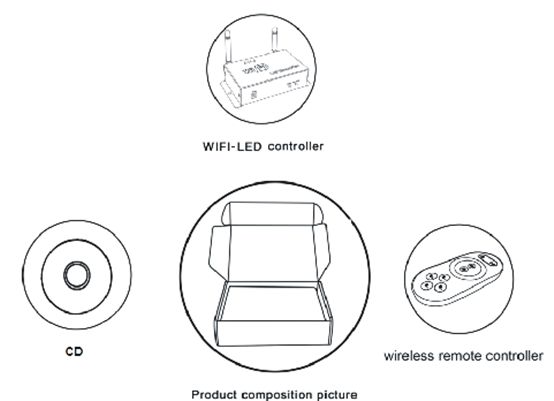
Product composition
|
LED-WiFi controller |
It is the core of the entire product and is responsible for receiving control signals and controlling LED devices.
|
|
RF remote control |
If you don't need a mobile phone as a remote control, you can choose an RF remote control to control the LED |
|
One CD |
Mobile phone software including ios operating system and Android operating system |
Specifications Download 
Interface description
1.Install ANT
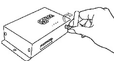
ANT installation diagram: Install the WiFi antenna clockwise, and remove the antenna counterclockwise.
2.Power supply and LED equipment
This connector structure belong to drawer structure, the device interface of power supply and LED is together, four interface one the left side (3. 2. 1. V+) is connect led equipment,the fifth interface is connect the anode V+ of power supply, the sixth interface is connect the cathode V_ of power supply. According to the rated voltage of led lamp, we supply power to controller,and the rated voltage of controller is 24V. As follows:
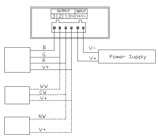
Instructions for use
LED-WiFi controller function description
1. Description of working status
|
Indicator Light |
Menu |
|
Power |
Power indicator, steady light means normal power supply
|
|
Wifi |
Always on when idle, wifi data flashes in, ssid with wifi off
|
|
Link |
Received data begins to flash |
|
RF |
The correct wifi data enters flashing, idle off, there is a remote control to control flashing,
|
2.Set SSID number
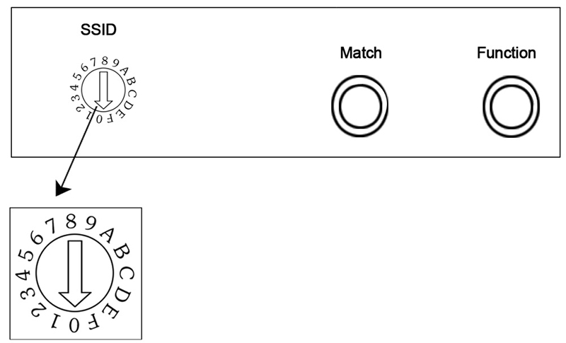
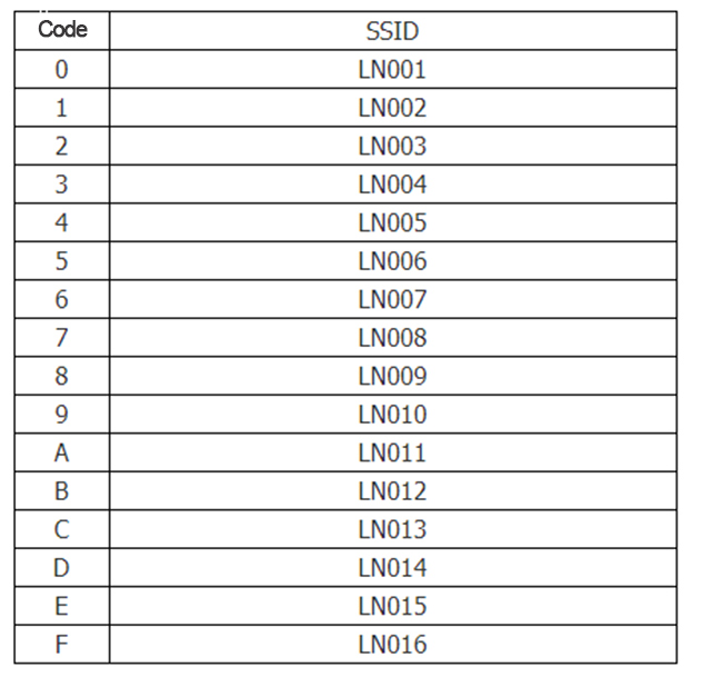
The coding switch we choose is used to set the Ssid number of the LED-WiFi controller. The corresponding table is shown in the figure. There are 16 numbers from 0 to 15, so our Ssid numbers are fixed at LN001 to LN016. That is to say, with our products, 16 isolated LANs can be set in the same small area. Once the DIP switch is toggled and changed, the Ssid number will be modified immediately, so you should pay attention to your mobile phone need to search for the connection again.
3. Connect LED and power supply port
The LED interface needs to be connected to the RGB three-way LED device in the CD mode page, the cool white and the warm white two-way LED device group in the CT mode, and the monochrome LED device in the DIM mode.
4. Match key function
When using the controller and the remote control for the first time, the remote control cannot be remotely controlled due to the mismatch between the controller address and the remote control address. In this case, use this key to match the two addresses.
How to use: First, press the "Match" button of the controller and press any button on the remote control for more than 2 seconds. Release the "Match" button, and the match is complete.
5. Function key function
The "Function" key is a composite key with functions of switching and mode switching.
Function description: long press (above 2S): switch;
Short press (within 1S): mode switch.
Remote control function description
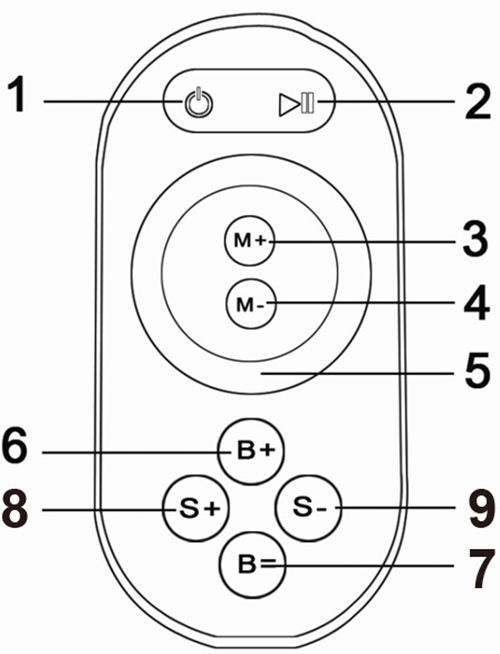
1. Switch key 2. Pause key
3. Mode + 4, Mode-
5. Color ring key 6, brightness +
7, brightness- 8, speed +
9. Speed-
There are 64 touch buttons (points) on the touch remote control panel. The functions of each button are as follows:
1. Switch key, in any state, the controller output can be turned on or off;
2. Pause key, in dynamic mode, can stop the controller in the current state;
3. The key has two functions:
① Mode plus selection key, that is, when the current control mode is the pulley mode (color), if you need to realize the mode (color) in the controller, you can press this key.
② Mode switching key, that is, when the current control is M key mode, the mode (color) specified in the M+ key mode table can be switched.
4. This key has two functions:
① Mode minus selection key, that is, when the current control mode is pulley mode (color), if you need to realize the mode (color) in the controller, you can press this key.
② Mode switching key, that is, when the current control is M key mode, the mode (color) specified in the M-key mode table can be switched.
5. Color wheel touch keys, static mode selection keys, up to 55 touch points.
This key has two functions:
①Puller static color selection key, that is, when the current control mode is the M key mode (color), if you need to achieve a static color on the pulley, you can press this key.
②Pulley color switching key: it can be switched from 55 static colors (the color shown by the pulley).
6. Output brightness control key, each time the brightness level is increased by 1, a total of 100 levels;
7. Output brightness control key, each time the brightness level is reduced by 1, there are 100 levels in total;
8. Output speed control key, each time you press the speed level plus 1, a total of 100 levels;
9. Output speed control key, the speed level is reduced by 1 each time it is pressed, a total of 100 levels;
Power management: Stop using the remote control for more than 20s, the remote control will automatically enter the standby state (not touchable state) to extend battery life; the camera will return to normal working state (touchable state) after a little shaking.
Note: This remote control is only for RGB mode
Controller built-in mode table
1. RGB control mode table:
|
Mode Number |
Features |
Remarks |
|
1 |
Static red |
Adjustable brightness, not adjustable speed |
|
2 |
Staticgreen |
|
|
3 |
Static blue |
Adjustable brightness, not adjustable speed |
|
4 |
Static yellow |
|
|
5 |
Static purple |
|
|
6 |
Static cyan |
|
|
7 |
Static white |
|
|
8 |
Three-color jump |
Adjustable speed, brightness is not adjustable |
|
9 |
Three-color gradient |
Adjustable speed, brightness is not adjustable |
|
10 |
Seven colors jump |
Adjustable speed, brightness is not adjustable |
|
11 |
Seven-color gradient |
Adjustable speed, brightness is not adjustable |
Color temperature control mode table:
|
Mode Number |
Features |
Remarks |
|
1 |
Cold white |
Adjustable brightness |
|
2 |
80% cool white |
|
|
3 |
60% cool white |
|
|
4 |
40% cool white |
|
|
5 |
20% cool white |
|
|
6 |
Pure white |
|
|
7 |
20% warm white |
|
|
8 |
40% warm white |
|
|
9 |
60% warm white |
|
|
10 |
80% warm white |
|
|
11 |
Warm white |
Dimming control mode table:
|
Mode Number |
Features |
Remarks |
|
1 |
1% |
Brightness ratio |
|
2 |
10% |
|
|
3 |
20% |
|
|
4 |
30% |
|
|
5 |
40% |
|
|
6 |
50% |
|
|
7 |
60% |
|
|
8 |
70% |
|
|
9 |
80% |
|
|
10 |
90% |
|
|
11 |
100% |
Typical application
1. Connect three channels LED instruction

When connect three channels LED, you should put the Dream Color software switch to CD mode to use,only under this mode,you can control the LED's color,brightness and speed.Color disk adjust the color(Adjust process can be seen in the upper left corner R, G, B numerical with change),speed/brightness item adjust speed and bright("M"set the LED dynamic effect,"M"adjust the LED dynamic change.
2. Instructions for connecting two LEDs
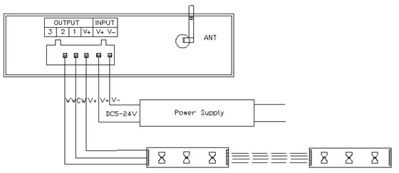
If you connect two LEDs, you should switch the Dream color software to the CT mode page. Only in this mode page can you normally control the LED color temperature, brightness, and color temperature shortcut key settings. The color wheel adjusts the color temperature (at the same time, the CW and WW values at the upper left change with the change), the brightness bar adjusts the brightness, and the special color temperature state is set under the ‘M’ key
Instructions for connecting all the way LED
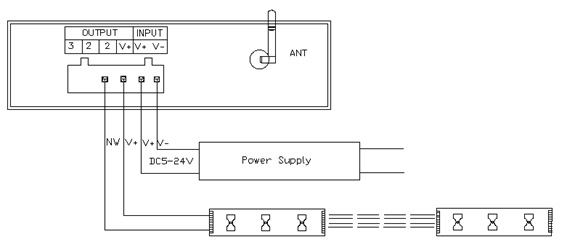
If you connect an LED all the way, you should switch the Dream color software to DIM mode. In this mode page, the color wheel is used to control the brightness of the LED. The NM value in the upper left corner of the adjustment process also changes.