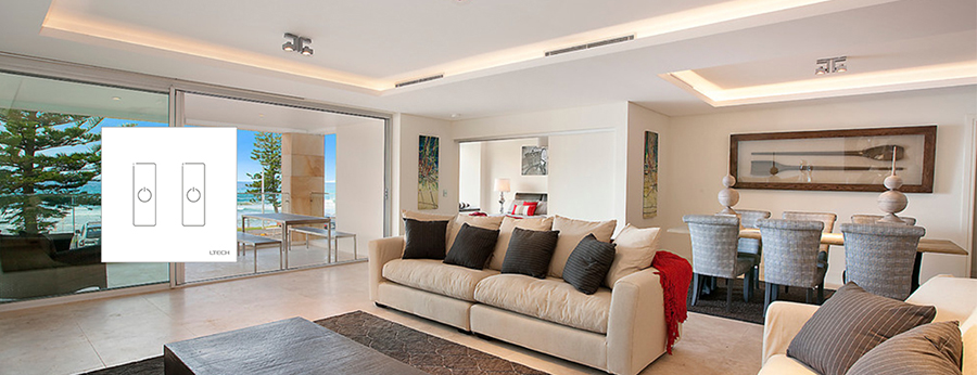
Go to Top
SuperLightingLED
SUPERLIGHTINGLED CO., LTD
Web: www.superlightingled.com
Email: [email protected]
Date: 2026-11-03 | ID: 2187

DALI touch panel EDA2 For LED Strip Light

MODEL: EDA2
Price based on selections below:
$46.99
AvailabilityIn Stock
ConditionBrand New
Technical Specifications

The EDA2 is an in-wall master dimmer touch panel engineered for two-channel management across any standard DALI lighting system. Compliant with the international DALI digital addressable lighting interface protocol IEC62386, this touch panel dimmer sends switching and dimming commands directly over the 2-wire DALI signal bus. Operating without an external line-voltage transformer or auxiliary power wire, the unit draws a nominal 6mA static current directly from the 16V DC bus. Two responsive capacitive touch keys provide dedicated control over two separate lighting circuits, downlights, or runs of single color LED strip lights. Each key supports dual actions: a rapid tap toggles fixture power on or off, while a continuous press ramps brightness smoothly up or down. With hardware rotary switches for instant physical addressing, the EDA2 delivers robust lighting DALI system integration for architectural interiors.
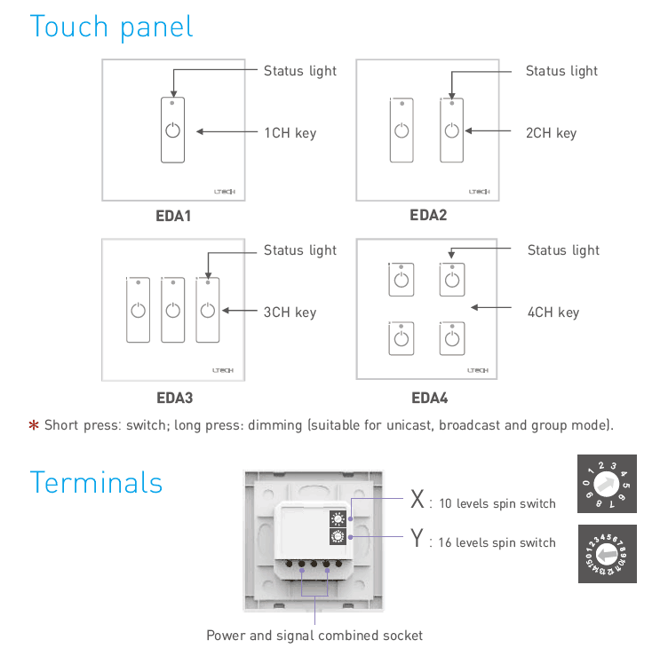
Rear terminal socket and dual rotary address selection spin switches X and Y on the EDA2 controller
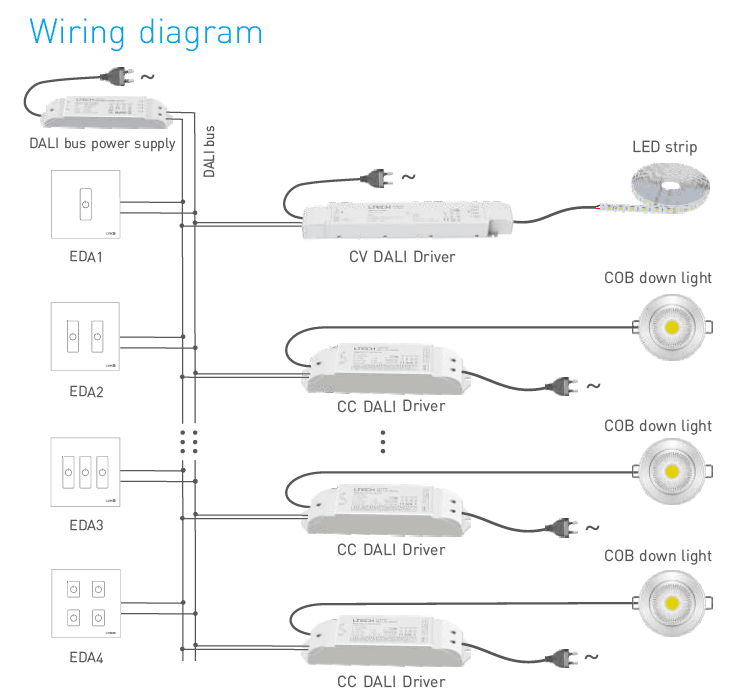
DALI bus wiring diagram connecting EDA2 touch panel with constant voltage and constant current drivers

Key Features

Dual-Channel Independent Control

Features two dedicated capacitive touch keys that manage two separate DALI light channels, groups, or scenes independently.

Standard IEC62386 Compliance

Adheres to international DALI standard protocol IEC62386 to guarantee interoperability with certified DALI drivers and ballasts.

Direct DALI Bus Powering

Pulls power directly from the 16V DC DALI signal line with a low static draw of 6mA, eliminating extra high-voltage wiring.

Four Operational Addressing Modes

Enables unicast, group, scene, and broadcast operational modes selectable directly via rear rotary dials.

Hardware Rotary Addressing

Includes onboard rotary spin switches X (0 to 9) and Y (0 to F) for physical address configuration without software tools.

Standard 86-Style Enclosure

Measures 86×86×37 mm, designed for flush installation into standard European and 86-type electrical back boxes.

Integrated Status Indicators

Equipped with dual LED indicator lights on the front glass face to signal active channel output and feedback.
Technical Highlights

  • Eliminates local mains wiring: Powered entirely by the 2-wire digital bus at 16V DC, consuming 6mA during active static state and dropping to 4mA in standby.
  • Precision dimming actions: Short press executes immediate power switching; sustained press initiates smooth brightness dimming across 0.1% to 100% ranges.
  • Manual addressing logic: Rotary switch X selects the operational mode (0–6 for unicast addressing 0–63; 7 for group mode 0–15; 8 for scene mode 0–15; 9 for broadcast mode).
  • Rotary switch Y sets the secondary numeric digit or hexadecimal channel value (0–F) for accurate fixture assignment on the bus.
  • Operating temperature resilience from -30℃ to 55℃ ensures steady digital signal transmission in unconditioned commercial equipment spaces.
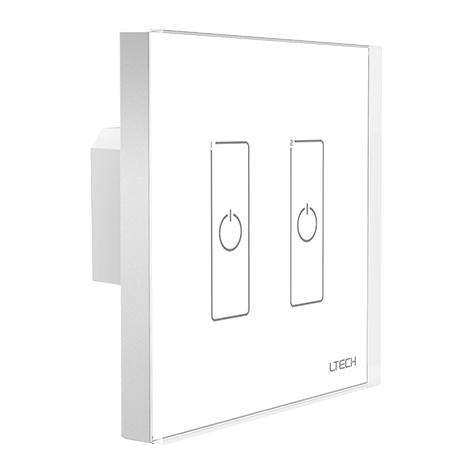
Front glass faceplate of the EDA2 2-channel DALI dimmer touch panel with blue status indicator lights

Product Specifications

ParameterDetails
Product ModelEDA2
Product TypeDALI Master Wall Dimmer Touch Panel
Communication ProtocolDALI IEC62386
Power Supply InputDALI Bus Power
Bus Operating Voltage16V DC (Standard DALI Bus Range)
Static Current Draw6mA @ 16V
Standby Current Draw4mA @ 16V
Control Channels2 Channels (EDA2)
Output SignalDALI Digital Signal
Switching / Dimming LogicShort press: toggle ON/OFF; Long press: dimming ramp
Control Modes SupportedUnicast (0-63), Group (0-15), Scene (0-15), Broadcast
Address Setting MethodDual Rotary Spin Switches (X: 10 levels, Y: 16 levels)
Operating Temperature-30℃ to 55℃
Dimensions (L × W × H)86 × 86 × 37 mm
Package Dimensions113 × 112 × 50 mm
Gross Weight200 g
Compatible Junction BoxEuropean Standard / 86 Style Back Box
DALI touch panel EDA2 For LED Strip Light - photo 1
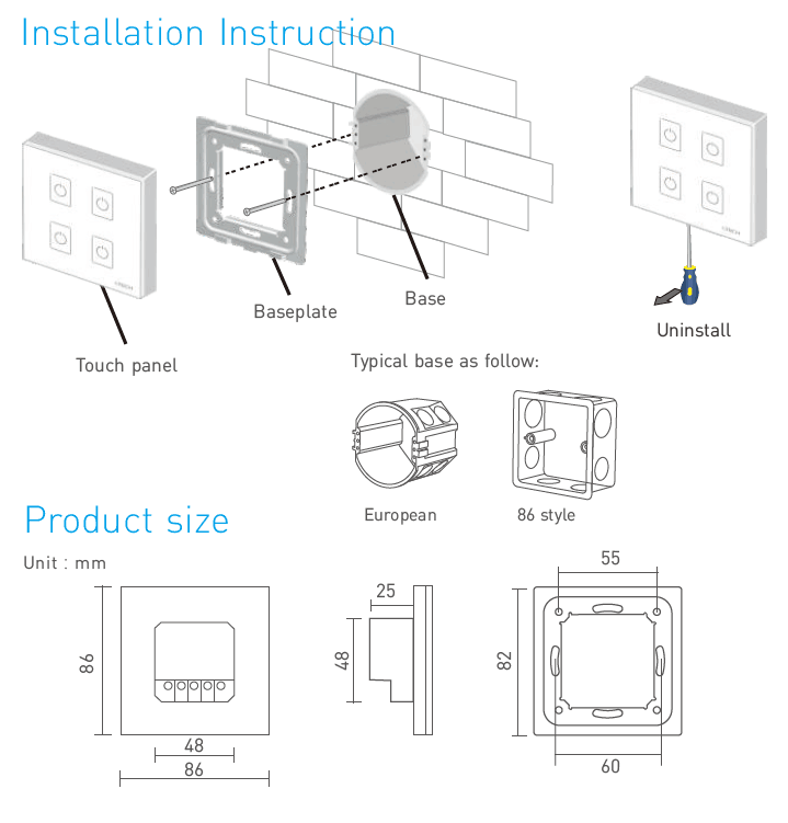
External dimensions 86x86x37mm and European standard 86-style wall mounting baseplate diagram

Application Scenarios

Commercial Office Dual-Zone Lighting Manage individual lighting circuits such as perimeter ambient cove lines and workstation linear pendants from a single touch panel dimmer. The 2-channel layout lets occupants toggle or dim task lighting separately from primary ceiling fixtures.
Residential Linear Accent & Downlight Control Ideal for spaces requiring grouped control over architectural lighting, such as kitchen downlights paired with under-cabinet single color LED strip lights. Powered directly by the bus, the wall unit mounts cleanly into standard wall boxes.
Conference Rooms & Executive Boardrooms Control presentation lighting and perimeter wall washers independently. Presenters can short-press to turn off front fixtures during projection while long-pressing channel 2 to dim surrounding fixtures to 20% output.

How to Control & Use This Controller

  1. Confirm DALI Bus Power: Ensure the 2-wire DALI network is energized by an approved 16V DC DALI bus power supply before connecting control panels.
  2. Wire the Signal Terminals: Strip 6–8mm of insulation from the 2-core DALI bus cable and insert the leads into the rear combined power/signal terminal block. DALI wiring is non-polarized, so polarity reversal will not damage the unit.
  3. Set Operating Mode with Switch X: Use a flathead precision screwdriver to rotate spin switch X. Select positions 0 to 6 for unicast addressing, 7 for group mode, 8 for scene mode, or 9 for broadcast mode.
  4. Set Target Channel Address with Switch Y: In unicast mode, the initial address equals X*10 + Y (e.g., X=4, Y=0 sets address 40). In group or scene mode, position Y sets the specific group or scene ID from 0 to 15.
  5. Install Mounting Base: Detach the glass faceplate from the baseplate using a pry slot at the bottom, fasten the baseplate into the 86-style wall back box with the supplied screws, and snap the front touch panel into place.
  6. Test Key Operation: Short press key 1 and key 2 to confirm toggling of the corresponding DALI light fixtures. Long press each key to verify continuous dimming up and down.
⚠ Precautions
  • Do not connect 100-240V AC mains electricity directly to the EDA2 terminal pins; the device is powered strictly via the DALI bus line.
  • Total bus current draw must remain within the limits of your central bus power supply (typically 250mA max for a DALI line; EDA2 draws 6mA).
  • Keep total DALI bus line wire runs under 300 meters using minimum 1.5 mm² (16 AWG) copper wire to prevent signal voltage drops below 9.5V.
  • Ensure rotary dials click cleanly into slot notches; leaving a rotary switch between two positions will lead to addressing misreads.
  • Always isolate bus power during terminal connection or disconnect to prevent signal glitches on connected drivers.

What's in the Box

  • ✓1 × DALI Touch Panel EDA2 2-Channel Dimmer Controller
  • ✓1 × Wall Mounting Baseplate
  • ✓1 × User Operating Instruction Manual

⇩ Downloads & Documents

PDFEDA2

Frequently Asked Questions

Q: Does the EDA2 touch panel dimmer require a separate 12V or 24V power supply?

A:No. The EDA2 is powered directly from the standard 16V DC DALI bus line, drawing 6mA of static current. It does not require external low-voltage power adapters or AC line voltage.

Q: What is the difference between EDA1, EDA2, EDA3, and EDA4 models?

A:The models differ strictly by the number of touch control keys: EDA1 controls 1 channel, EDA2 controls 2 channels, EDA3 controls 3 channels, and EDA4 controls 4 channels.

Q: How does the short press and long press operation work?

A:A short press (under 0.5 seconds) on either touch key toggles the assigned fixture ON or OFF. A sustained long press ramps the light level continuously upward or downward.

Q: How do the rear rotary switches configure unicast addressing?

A:Switch X represents tens (0–6) and switch Y represents units (0–9, continuing A–F). The initial channel address equals X*10 + Y. For example, setting X to 4 and Y to 0 assigns the controller to DALI address 40.

Q: Can the EDA2 control DALI group and scene modes?

A:Yes. Turning rotary switch X to position 7 sets group mode, and position 8 sets scene mode. Dial Y then designates the target group number (0–15) or scene number (0–15).

Q: What happens if unicast address calculation exceeds 63?

A:According to the IEC62386 standard, the maximum unicast address is 63. If your rotary combination totals a value beyond 63, the internal microcontroller defaults the address to 63.

Q: Is the DALI bus wiring polarized when connecting to the EDA2 terminal block?

A:Standard DALI control signals are non-polarized. You can attach the two bus wires to either terminal on the EDA2 rear socket without risk of connection faults.

Q: What size back box is needed for wall mounting?

A:The EDA2 has an 86×86 mm outer frame with a 37 mm total depth, fitting standard European 86-style flush-mount wall junction boxes.


© 2026 SuperLightingLED. All specifications are subject to change without notice.