

| Select Applied to: | Addressable LED Strip - 3 pin (Base) |
|---|---|
| Select Kit: | Controller (Base), Controller + GPRS Receiver |
| Select Operating Voltage: | 5/12/24 VDC (Base) |
| Availability | In Stock |
| Condition | Brand New |
K-8000D has beed discontinued now, you can use K-8000C to replace it.
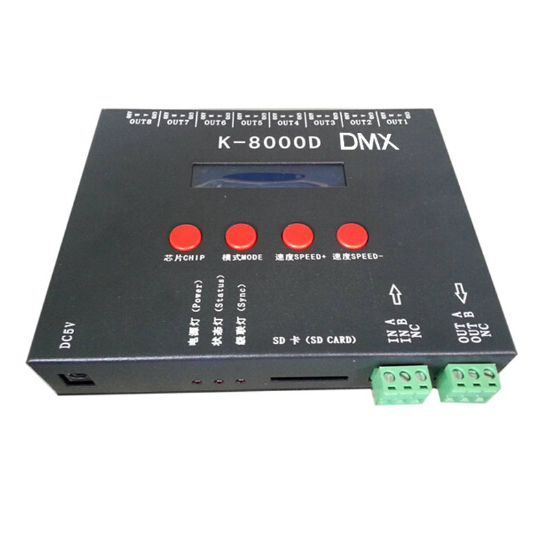
K-8000D system features
1,32 level -65 536-level grayscale control, software Gamma correction process.
2,supports a variety of point, line, surface light source, supports a variety of rules, shaped handle.
3,the controller 8 output ports, with each port maximum 512 lights.
4,the controller can use more than one cascade, Taiwan and Taiwan cascade distance of up to 200m; play content stored in the SD card.
5,K-8000D store up to 30 files.
6,K-8000D has joined the screen, the controller can be encrypted.
Notes: 1,requires the use of global wireless GPS synchronization, channel distributor and timing console when playing contact sales or technical support for further details
Support chips
0 DMX 250Kb (International standard DMX 512 (1990))
1 DMX 500Kb
2 DMX 500Kb_CZF
3 UCS19,29 series; TM18 series; WS2811/2812; SM16703 etc the same agreement IC
4 UCS512_Addressing
5 WS2821_Addressing
6 DMX512A_Addressing
Screen printing meaning
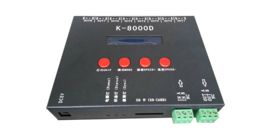
Buttons meaning:
|
Buttons |
Meaning |
||
|
CHIP |
Choose chip model and coding IC model |
00—03 means the support IC model 00——International standard DMX 512 (1990) 01——DMX 500Kbps 02——DMX Pure forwarding (DMX do not support lights) 03——UCS19 series and the same agreement IC Chip04—06 means the coding IC 04——UCS512 coding 05——WS2821 coding 06——SM DMX512AP coding |
|
|
MODE |
Switching file/Coding |
||
|
SPEED+ |
Speed up(channel plus) |
When the chip between 00-03,press SPEED+ and SPEED- at the same time, would enter file repeat mode. |
|
|
SPEED- |
Speed down(channel reduce) |
||
|
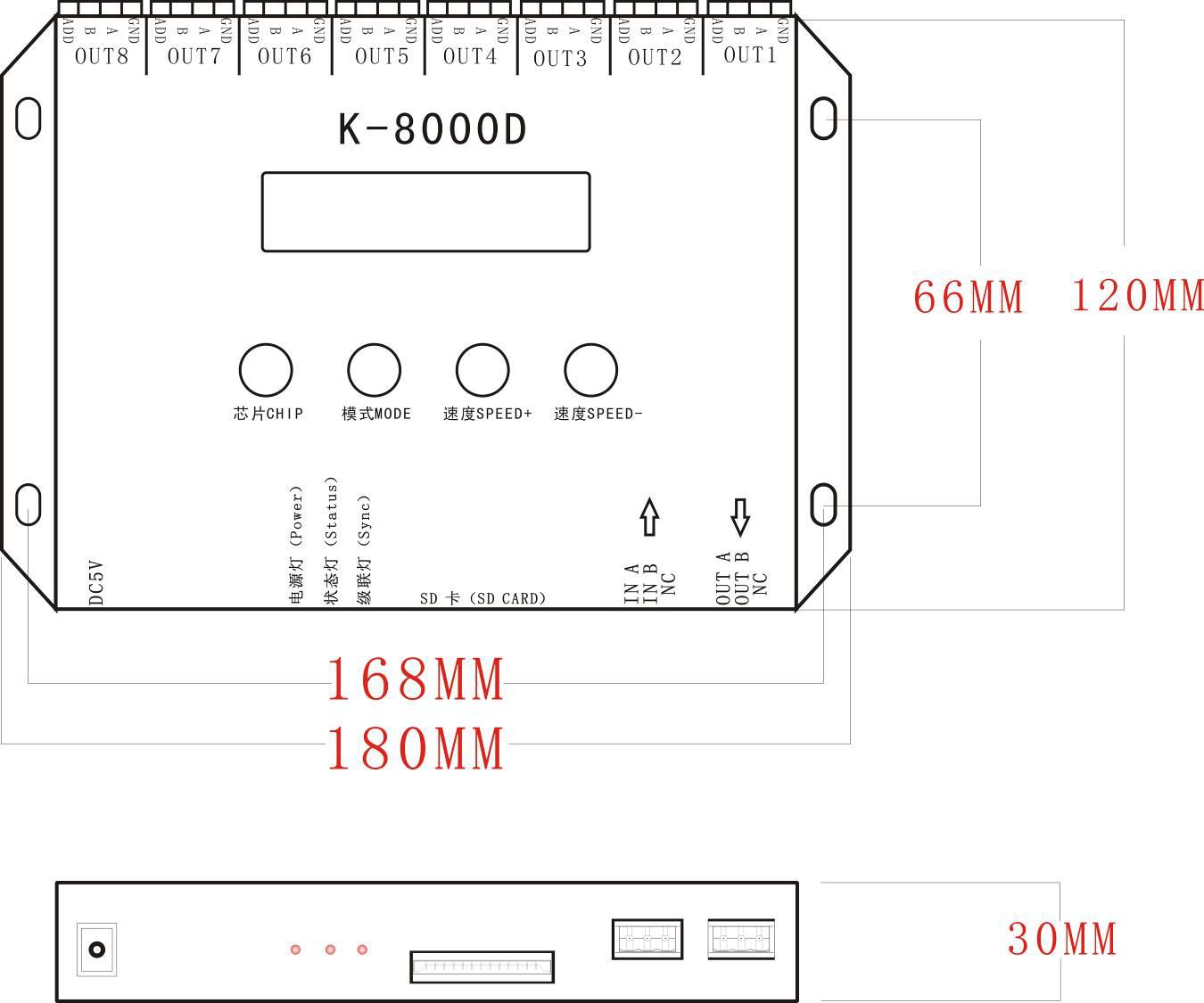
Supply power |
DC5V input |
|
POWER |
Power indicator light |
|
Status |
Status indicator light |
|
Sync |
The cascade indicator light |
|
SD CARD |
SD card slot |
Signal output(485 signal):
|
A |
Signal + |
|
B |
Signal - |
|
GND |
Ground line |
|
ADD |
Coding line |
Operation and Wiring
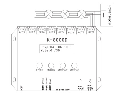
485 Differential wiring:
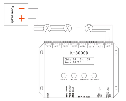
Non-differential wiring:
Operation
1. Wiring like the above diagram and start the controller,press”CHIP” button to change chips, adjust to 04-06 coding status(if the lights have coded well can skip step 1-3), as below:
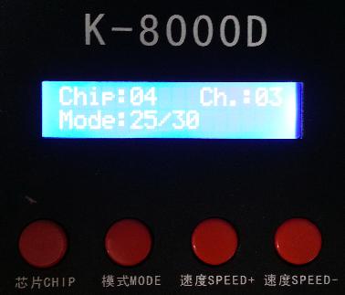
NOTE: The number 4 shows on CHIP position means UCS512 coding mode; 5 means WS2821 coding mode; 6 means SM512 coding mode.
2.Press speed + and speed - to set the address gap channel, like point light source is RGB three channels(the default interval are three channels), six section line are 18 channels, and so on.
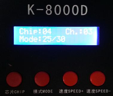
NOTE: If can not understand how to set the channel, welcome to contact teh corresponding sales man or technical staff.
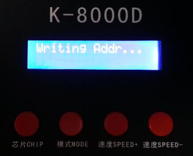
3. Press “MODE” sratr to coding, at this time, the digital screen of MODE would display as”Writing Addr...”, now it is coding, when it finished, the LCD screen would appear Writing OK.
4. After coding, power the light again, press “CHIP” and change to 0, it would be international standard DMX512(1990) agreement play mode. At this time press MODE and SPEED button can switch play mode and adjust speed respectively, like below:
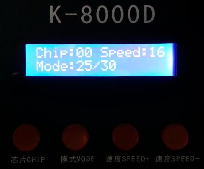
NOTE: When the chip is 00-03, press MODE button for eight seconds can direct write address to UCS512, the interval is three channels.
Specific parameter
Storage card:
Type: SD card
Volume: 128MB—2GB
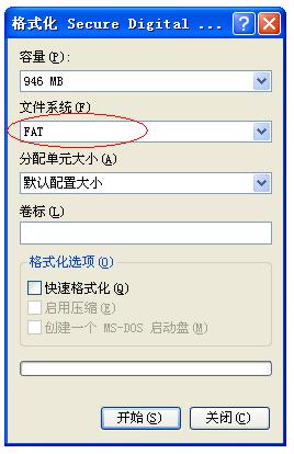
Format: FAT
Storage file: *.led
Physical parameters:
Working temperature: -30℃—85℃
Working power: DC5V input
Power: 3W
Weight: 0.8 Kg
Size: (L x W x H)
The words explain under encryption conditions
|
Password is OK |
Password is normal! |
|
Num |
The remaining boot times |
|
Password exist |
Password has exist |
|
Can't repeated |
Can not repeat the password |
|
Set Password OK |
Set password successfully |
|
Clear Pwd OK |
Delect the password successfully |
|
Pwd not right |
Password is not correct |
|
No Password |
Password is not exist |
|
Has expired! Contact factory |
Password expired, contact the factory |
NOTES
1. Before you copy files to the SD card, you must format the SD card, please note, each time you copy the files should format the SD card.
2. The SD card shoule be formated as “FAT”, as below:
NOTE: SD card in the controller can not be hot-swappable, that is each time plug SD card, you must disconnect the power of the controller.
GPS wireless synchronization solution
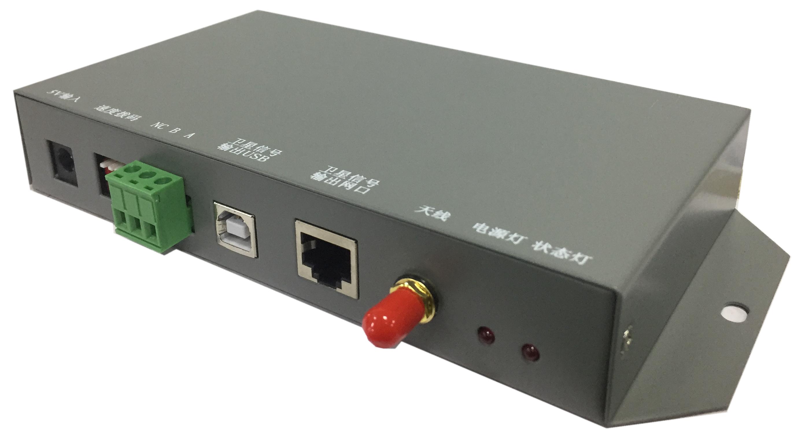
Product Description
1. DC5~24V,8 channel,K-8000D with SD card pixel programmable controller support standard dmx512 chip/DMX512AP-N/WS2821A writer function for addressable led strip lights
2. Solve the problem that the controller and the controller cannot be synchronized due to the inability to install the cable between the building and the building.
3, take the GPS timing method, as long as the satellite signal can receive the synchronization between the controllers, globally available, the accuracy can reach nanoseconds.
4, GPS to the main control distance up to 100 meters.
5, the external antenna, the antenna and GPS synchronization mode separation, better, faster, more stable reception of satellite signals.
6, GPS has a learning function, can be synchronized within 2 hours after the signal is lost.
Note: The antenna of the GPS global synchronization module must be placed outdoors.
Product indication
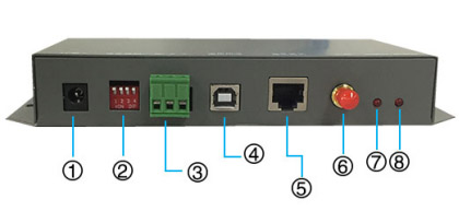
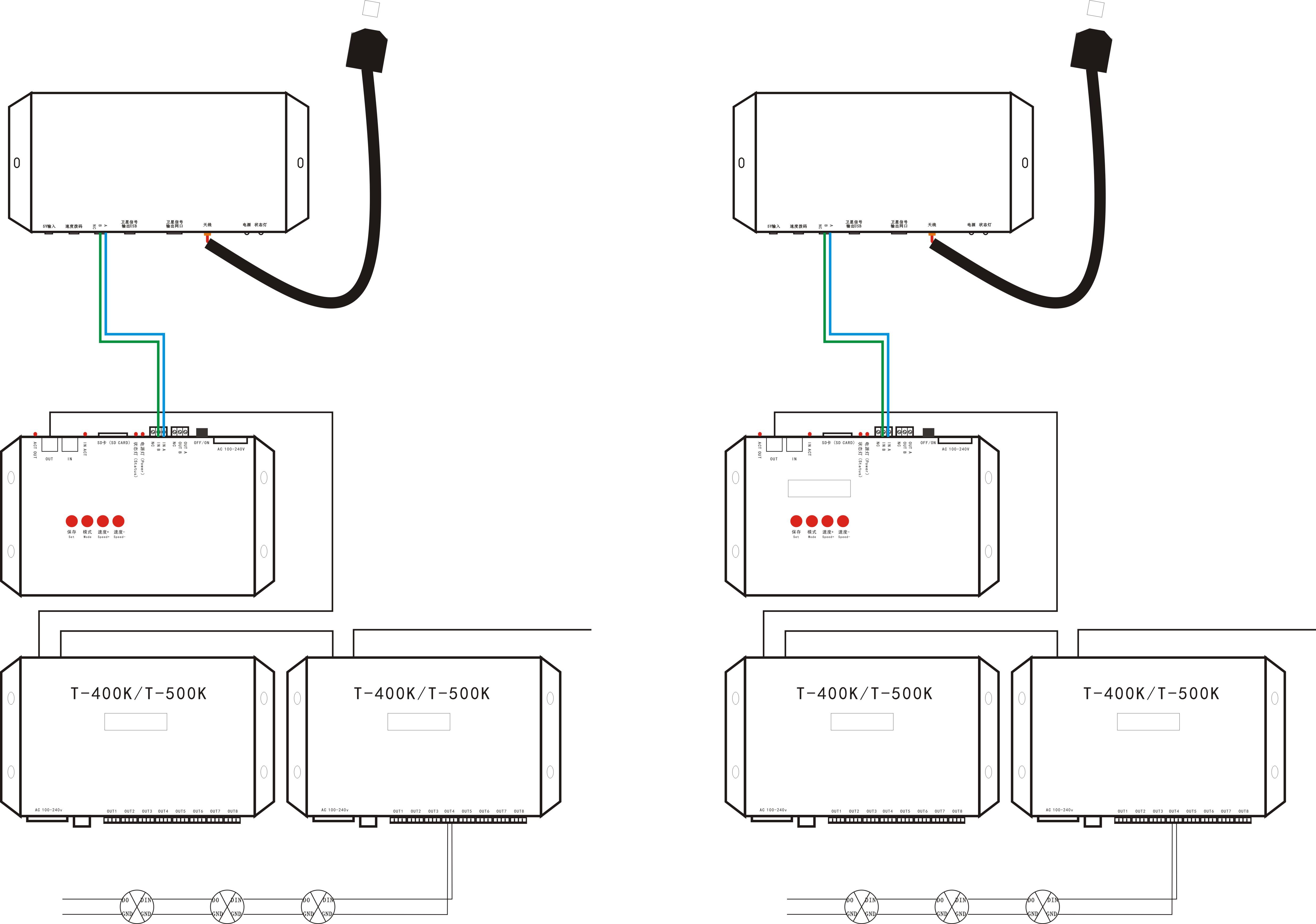
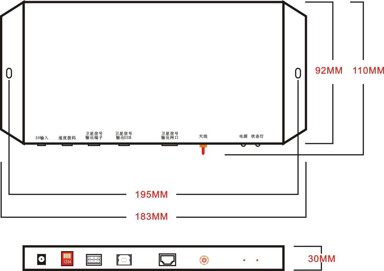
1. Power socket 2. Speed dial switch 3. Cascading terminal 4. Satellite signal output USB interface 5. Satellite signal output network port 6. Antenna interface 7. Power indicator light 8. Status indicator
Wiring diagram
Product specifications
Weight: 0.3Kg
Working voltage: DC5V
Power: 2W
Working temperature: -30 ° C - 85 ° C
Size: L*H*W
Speed dial switch settings
|
(1-4) |
Corresponding frame rate |
DIP switch status |
|||
|
0000 |
25frame/S |
Up |
Up |
Up |
Up |
|
1000 |
20frame/S |
Down |
Up |
Up |
Up |
|
1100 |
16frame/S |
Down |
Down |
Up |
Up |
|
1110 |
12frame/S |
Down |
Down |
Down |
Up |
|
1111 |
8frame/S |
Down |
Down |
Down |
Down |
Note: “0” means “ON” and “1” means “OFF”
Common problem handling
Question 1: Two or more GPSs are not synchronized after power-on
Answer: 1) The antenna of the GPS Global Synchronization Module is not pulled outdoors, and the synchronization module cannot receive the satellite synchronization signal.
2) Since the controller has too many pixels, it can't reach the frame frequency that the GPS global synchronization module can synchronize, and the second dial of the speed dial switch can be dialed down.