
0/1-10V CV LED Driver
9 productsSkyDance 0/1-10V CV LED Driver Series is designed to convert high-voltage AC mains power into regulated low-voltage DC power for constant voltage LED strip lighting, while accepting 0/1-10V dimming signals from compatible wall dimmers or smart control systems.
Combining AC-to-DC power conversion with integrated PWM dimming control, these 0/1-10V drivers provide a complete power supply and dimming solution for low-voltage LED lighting installations.
Available in 75W and 150W power ratings, with 12V and 24V DC constant voltage outputs, the series includes single-channel DIM drivers for single-color LED strips and a dual-channel CCT driver for tunable white LED strip lighting.
Five-in-One Dimming Compatibility: Unlike conventional LED power supplies that only support one dimming method, SkyDance 0/1-10V CV drivers support multiple control interfaces, including 0-10V, 1-10V, 10V PWM, Resistor Dimming, and AC Push-Dim. This flexibility makes them compatible with a wide range of conventional analog dimmers, rotary wall panels, touch dimmers, and momentary push-button switches.
Smooth & Precise Brightness Control: Depending on the model, the dimming range extends from 0–100% or 0.1–100%, providing smooth brightness adjustment down to very low light levels. Built-in over-temperature, overload, and short-circuit protection help maintain reliable operation under residential, commercial, and architectural working conditions.

75W 12V Dimmable LED Driver: 0-10V, PWM & Push-Dim Control

75W 12V LED Driver with 0-10V & SwitchDim | Universal Input

LPV-150M-12 0 to 10V 150W Dimmable Led Driver Constant Voltage

LPV-150M-24 Constant Voltage 150W 24V LED Strip Light Driver


40W 12V LED Driver: 0-10V, SwitchDim, Universal AC Input

40W LED Driver: 0-10V, Push-Dim, 24V CV Power Supply


How to Wire an AC-to-DC 0/1-10V Dimmable LED Driver
Unlike DC-to-DC 0/1-10V dimming drivers that require a separate low-voltage DC power supply, SkyDance AC-to-DC 0/1-10V CV LED drivers connect directly to AC mains power and internally convert high-voltage AC electricity into regulated low-voltage DC constant voltage output for LED strip lighting.
This integrated design eliminates the need for an additional external DC power supply, simplifying installation and reducing the number of components and wiring connections in the 0/1-10V lighting system.
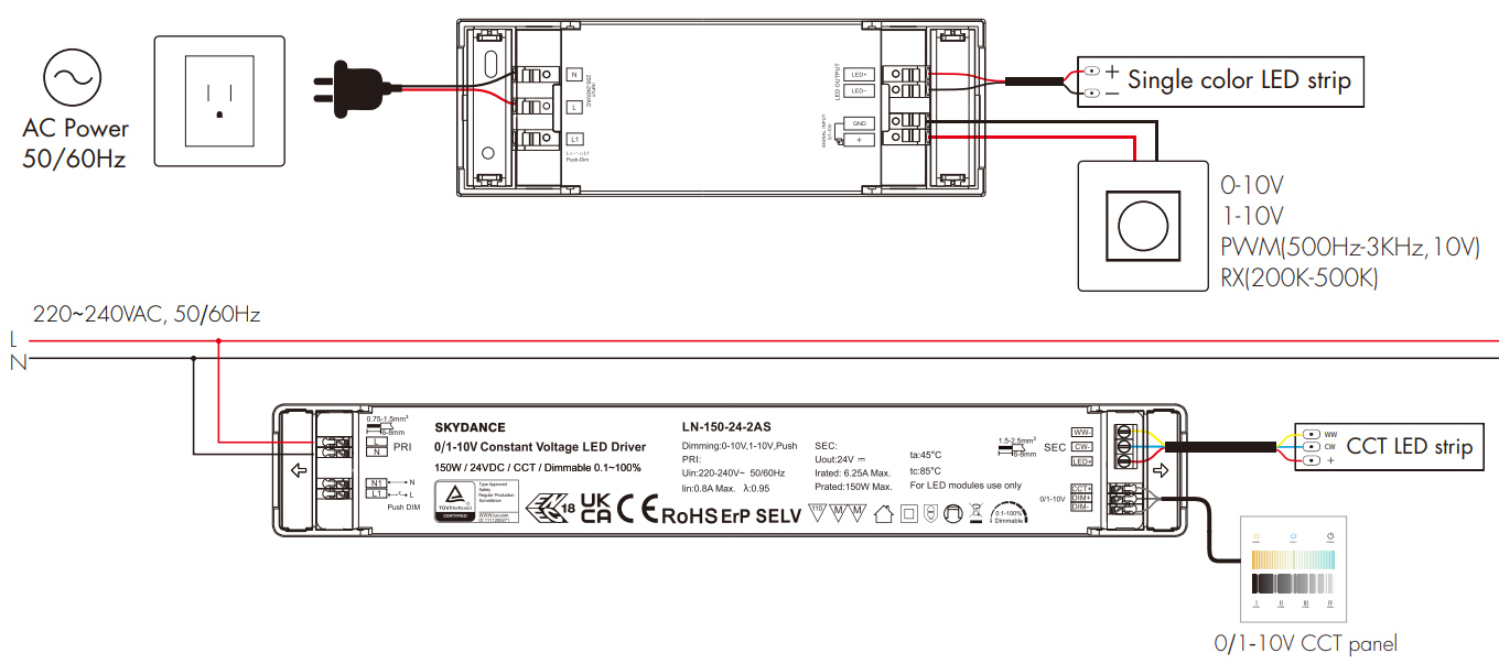
1. AC Mains Power Input
Connect the AC mains supply to the driver's designated AC-L and AC-N input terminals. The driver converts the incoming AC power into regulated DC 12V or 24V output, depending on the model.
Always verify the rated AC input voltage on the specific driver before installation. Input voltage ranges can vary between models.
2. 0/1-10V Dimming Signal Input
Connect a compatible 0-10V or 1-10V dimmer or smart controller to the driver's designated dimming signal input terminals.
The driver also supports other dimming interfaces, including 10V PWM, adjustable resistor (RX), and AC Push-Dim, depending on the model.
For AC Push-Dim operation, connect a compatible momentary push-button switch to the dedicated AC Push input terminals following the manufacturer's wiring diagram.
3. Low-Voltage LED Strip Output
Connect the regulated DC output terminals directly to the compatible constant voltage LED strips.
- Single-Channel DIM Driver: Connect the LED strip's positive and negative terminals to the corresponding LED+ and LED- outputs for single-color brightness control.
- Dual-Channel CCT Driver: Connect the tunable white LED strip to the LED+, WW-, and CW- output terminals. The two independently controlled channels adjust warm-white and cool-white output for brightness and color temperature adjustment.
Check the maximum output current and power rating before connecting the LED load.
AC mains wiring must be performed by a qualified electrician, with the power disconnected before installation or maintenance.
FAQ About 0/1-10V CV LED Driver
Direct engineering answers on wiring, load sizing, protocol compatibility, and multi-unit synchronization for 0/1-10V constant voltage LED drivers.
A 0/1-10V CV LED driver takes line-voltage AC power and directly outputs a constant DC voltage regulated by an analog 0-10V or 1-10V control signal. Unlike separate modular setups, this unit houses both the AC-to-DC transformer and the pulse-width modulation dimming circuit in one enclosure, accepting AC100-240V mains input and providing regulated 12V or 24V DC output. You wire your 120V or 230V mains hot, neutral, and ground directly to the AC input terminals, connect your 2-wire analog control circuit, and land your constant voltage LED strip lights straight onto the DC terminals.
A 0/1-10V CV LED driver combines an AC-to-DC power converter and a PWM dimming stage inside a single housing, eliminating an external DC power pack. Standalone 0/1-10V DC dimming drivers require a separate 12V or 24V industrial power brick upstream.
Wiring multiple 0/1-10V CV LED driver units to a single analog wall dimmer is straightforward because each driver consumes less than 0.1 mA on the control line. You daisy-chain the purple (positive) and gray or pink (negative) signal conductors in parallel across every driver in the zone. A standard 0-10V active wall switch capable of sinking 20 mA can easily supervise up to 50 of these drivers without signal degradation. Just remember that each driver still requires its own properly calculated AC mains feed, and DC outputs must never be tied together in parallel.
You can control a 0/1-10V CV LED driver wirelessly when it is paired with an RF-enabled 0/1-10V master controller or an RF wall station. When you connect our driver's 0/1-10V input terminals to one of our 0/1-10V panel dimmers that features a built-in 2.4GHz RF transceiver, handheld remotes or wireless kinetic wall switches can control the entire run. The wireless remote sends RF commands to the wall dimmer, and the dimmer alters the 0-10V control voltage fed into the driver's signal port. This gives you physical knob control and wireless handheld dimming on the exact same circuit.
Every 0/1-10V CV LED driver in this series features an active multi-mode dimming interface that natively reads 0-10V, 1-10V, 10V PWM, or resistance. The driver auto-senses whether you connect an active 0-10V source, an open-collector PWM signal generator, or a simple passive potentiometer between 10 kΩ and 100 kΩ. When connecting a rotary resistance potentiometer, adjust the resistance value across the signal terminals to vary output duty cycle from 0% to 100% without needing an external control voltage generator. This makes bench testing, machinery panel dials, and custom cabinet controls simple to wire.