
0/1-10V Dimmer
11 productsLTECH 0/1-10V Dimmers & Professional Lighting Control Interfaces
LTECH 0/1-10V dimmers are designed for architectural, commercial, hospitality, and high-end residential lighting systems that use the widely adopted 0-10V or 1-10V analog dimming standard.
Rather than focusing only on basic wall dimmers, LTECH develops a broader range of control interfaces, wireless dimming devices, signal converters, and smart control modules that allow traditional 0-10V lighting systems to work with modern RF, Bluetooth 5.0 SIG Mesh, DALI, DMX, and intelligent lighting-control technologies.
Depending on the model, LTECH products support 0/1-10V output, 10V PWM, Push DIM, RF wireless control, Bluetooth Mesh, and protocol conversion, providing a practical way to build new 0-10V lighting systems or upgrade existing installations without replacing the complete lighting infrastructure.
A typical installation can be as simple as:
- LTECH 0/1-10V Dimmer → 0/1-10V Dimmable CV Driver → LED Strip Lighting
- LTECH 0/1-10V Dimmer → 0/1-10V Dimmable CC Driver → CC Lighting Fixtures
- LTECH 0/1-10V Dimmer → 0/1-10V Dimmable DC Driver → DC Power Supply → LED Strip Lighting
The control signal adjusts the driver output while the lighting power remains handled by the compatible LED driver.
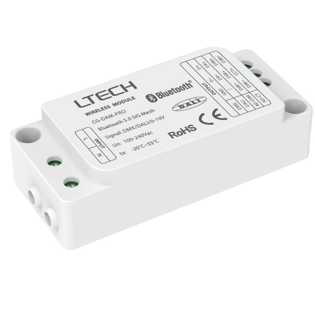
GC-DAM-PRO Bluetooth 5.0 Mesh LED Controller - DMX, DALI, 0-10V Output
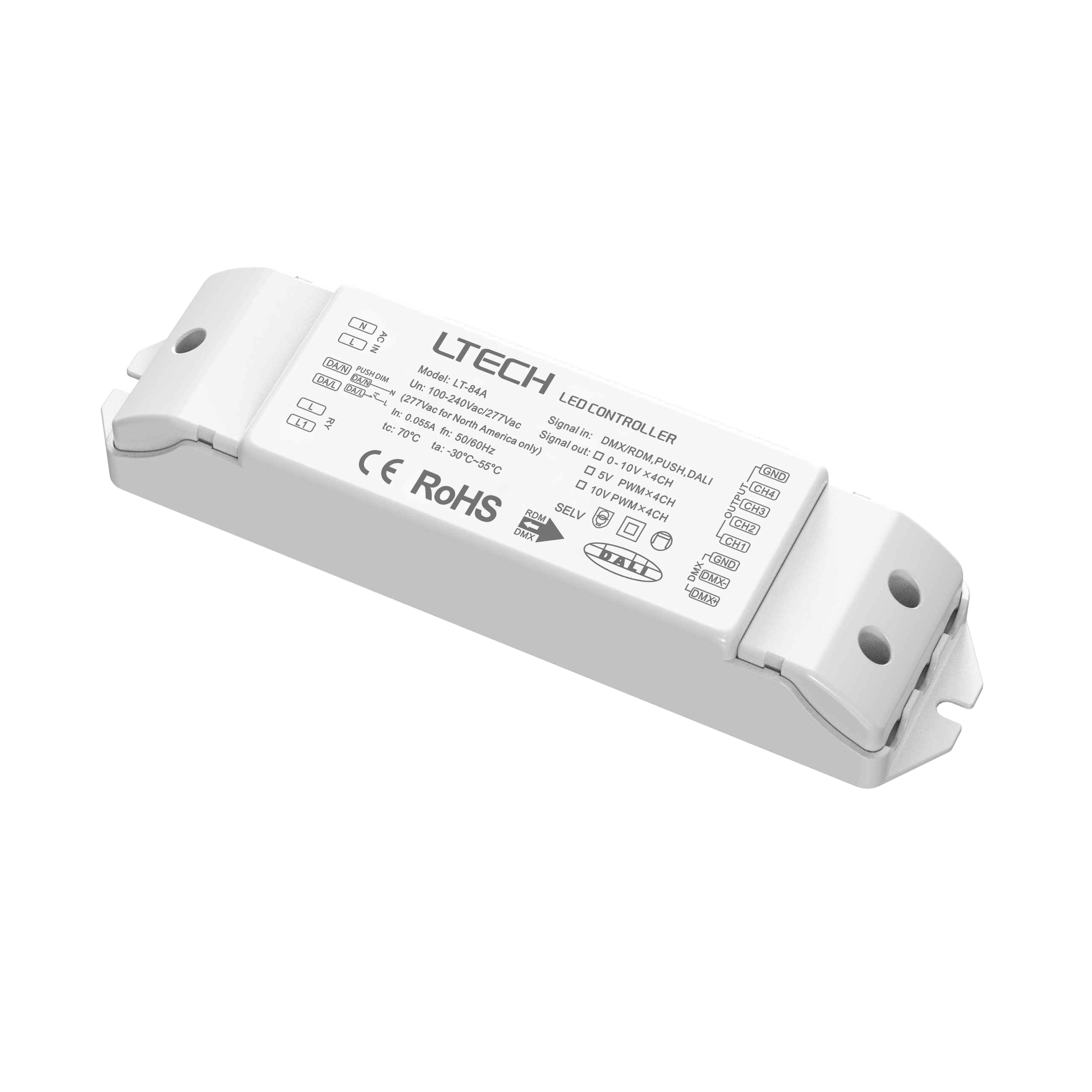
LT-84A Dmx Dali to 4CH 0-10V 5V PWM 10V PWM Converter
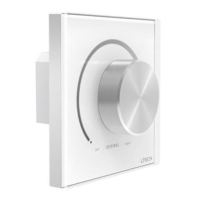
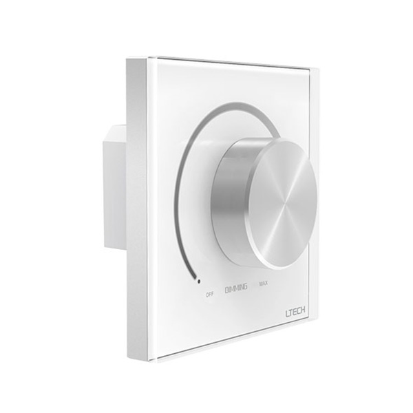
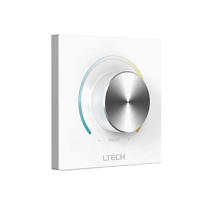
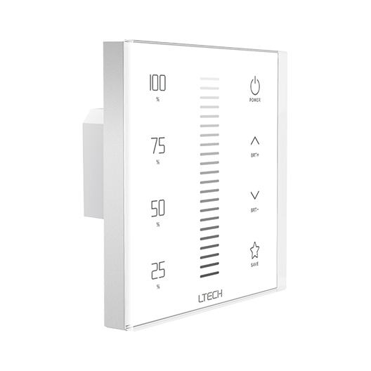
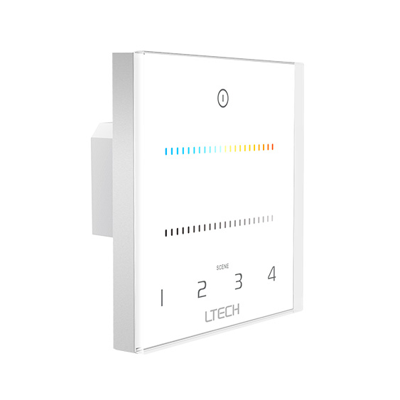
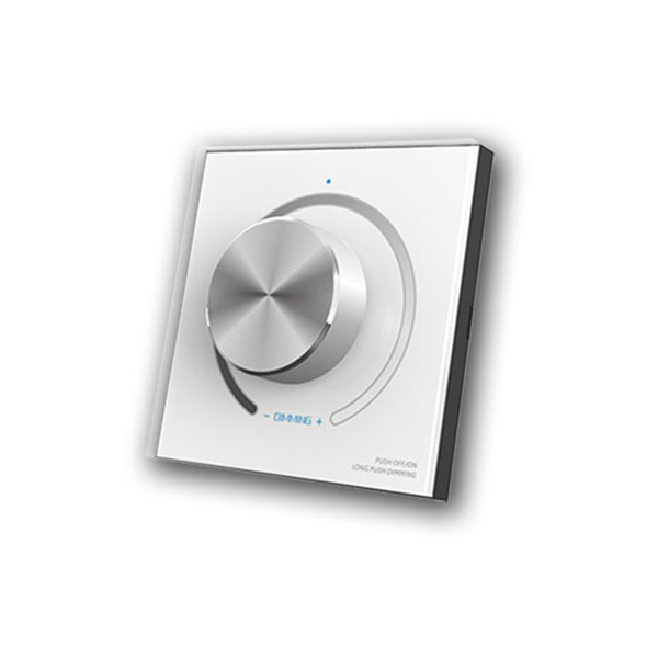
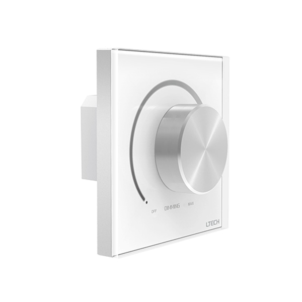
Connect 0-10V with DALI, DMX & Smart Control
A major strength of the LTECH 0-10V range is system integration. LTECH signal converters can translate DMX512 or DALI commands into 0-10V, 5V PWM, or 10V PWM control signals, allowing conventional analog-dimming equipment to become part of a larger professional lighting-control system.
Traditional 0-10V installations are often based on a single wired wall control. LTECH adds wireless flexibility through selected RF and Bluetooth-based control products, allowing compatible systems to combine fixed wall controls with remote or smart operation. This is especially valuable in buildings where different lighting zones use different control protocols and replacing every driver or fixture would be impractical.
FAQ About 0/1-10V Dimmer
Direct technical answers from our bench on wiring, signal sinking, and pairing 0/1-10V controllers with LED systems.
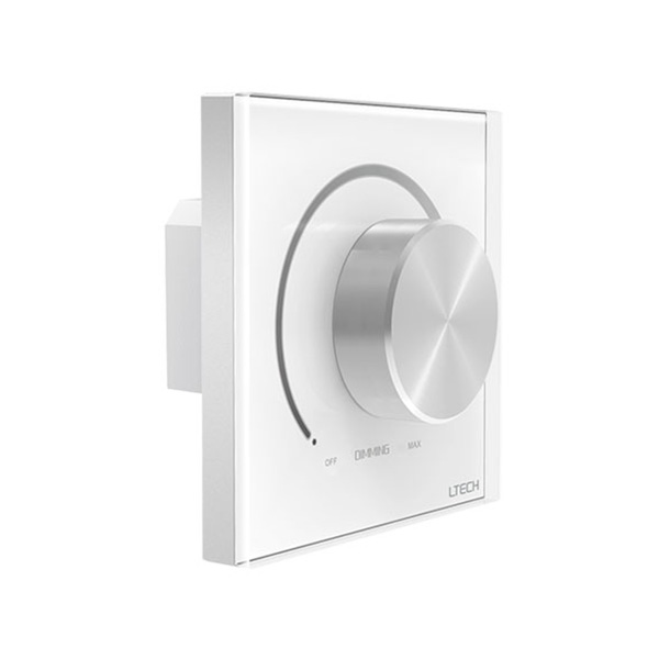
A 1-10v dimmer switch only drops control signal voltage to 1V, which tells the driver to run at its minimum output rather than shut off. Because the 1-10v specification never defined an electrical off state on the control pair, the driver requires a physical relay or switch contact to break 120V or 230V mains input. Our rotary models like the E610 and E610P integrate a 5A AC microswitch that disconnects line power as you click past the bottom detent. If your wall dimmer lacks that internal relay, wire an upstream disconnect switch or move to our true 0-10V panels.
A 0 10v controller generates or regulates the low-voltage control signal, while a dimmable driver takes line voltage and converts it into constant voltage or constant current to illuminate your LED strip. Many contractors confuse the two because both carry 0-10V labels. The wall panel or signal module sends a 0 to 10V DC reference down a 2-wire pair drawing less than 2mA per unit. That control signal connects to constant voltage 0-10V drivers, which deliver the actual 12V or 24V DC operating current that feeds the tape.
You can connect as many drivers as the dimmer's current sinking rating allows, which is typically 20 to 50 drivers on a standard 0 10v dimmer module. Most 0-10V LED power supplies source roughly 0.5mA to 1mA across their purple and pink signal lines. A controller rated for 50mA sink capacity, such as the E610P-RF, easily manages 50 standard drivers wired in parallel. If you exceed that current sink limit, signal voltage sags across the line, preventing the fixtures from reaching full 100% output even when the knob is turned to maximum.
Low-end flicker on a 0-10v dimming line is usually caused by electromagnetic noise induced on unshielded control wiring or a mismatch with an entry-level driver's internal PWM curve. Running control signal lines right next to 120V or 277V feeds causes 60Hz induction, which wobbles the control voltage when it drops near 1V. Unlike phase-cut issues covered in our TRIAC dimming guide, 0-10V flicker is cured by separating wire runs, using twisted shielded pair, or swapping to drivers with deep 0.1% logarithmic dimming stages that filter noise.
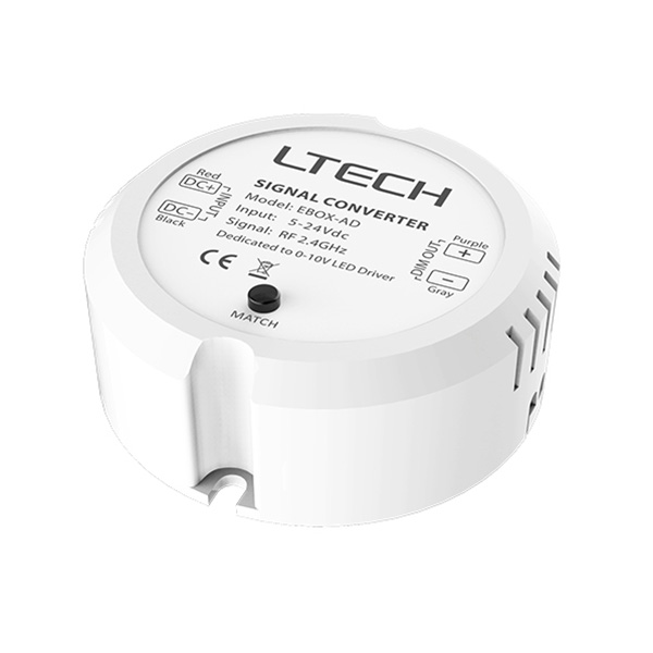
A standard 0-10V control varies steady DC voltage between 0V and 10V, whereas a 10v pwm dimmer pulses a 10V amplitude signal at variable duty cycles between 0% and 100%. While both control compatible commercial drivers, 10V PWM maintains signal integrity over significantly longer distances without suffering the resistive voltage drop that distorts analog DC lines. Modules like our EBOX-AD output 10V PWM signals, providing rock-solid dimming across up to 50 power supplies with zero signal degradation even at runs stretching past 100 meters.
Controlling dual-white tape requires two synchronized control channels, which you manage using a dedicated dual-channel 0-10v dimmer like our E610P-CT wall panel. One channel adjusts total lumen output from 0% to 100%, while the second channel shifts CCT balance between warm white and cool white without altering overall illuminance. The controller sends these independent signals to constant current 0-10V drivers or multi-channel constant voltage units, keeping your color temperature perfectly stable throughout the dimming cycle without cross-interference.
Light levels jumping or dimming in reverse happens when the control pair is wired with reverse polarity or when a current-sinking 0 10v controller is paired with a driver that also requires external current. Standard commercial 0-10V drivers source current, so swapping the purple (positive) and pink or gray (negative) leads causes the driver to read 0V as 10V, flipping the dimming curve. Verify polarity with a multimeter: at full turn clockwise, you should measure close to 10V DC across the terminal block.