
DMX Fiber Optic Engine
8 productsDMX (Digital Multiplex) fiber optic illuminator is a lighting device that realizes luminaire control through digital multiplex technology. DMX protocol was originally designed to solve the problem of equipment interoperability in stage lighting systems and has now become the standard in lighting industry.
-
Integration of a large number of fiber illuminators and control equipment, making the fiber optic lighting system layout more concise and more convenient to control fiber lights
-
Can achieve precise control of individual fiber light sources, flexible adjustment of brightness, color, dynamic effects, etc.
-
It is the best choice for commercial lighting, large building lighting, and landscape lighting
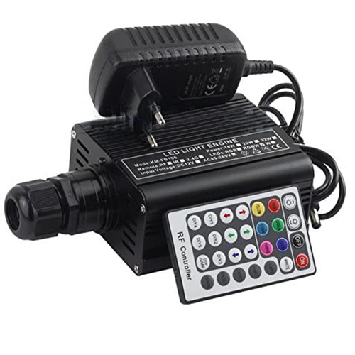

Double Head 32W RF DMX512 RGB LED Fiber Optic Light Engine

Commercial 45W DMX Fibre Optic LED Starry Ceiling Light Machine

DMX-Controllable 45W RGB Optical Fibre LED Star Ceiling Projector


FAQ About DMX Fiber Optic Engines
Direct answers on DMX512 channel allocation, 24V wiring layouts, console addressing, and commercial fiber optic engine installation.
A DMX fiber optic engine is a specialized light source that uses standard USITT DMX512 digital protocol to control color mixing, overall dimming, and motorized twinkle wheels through an external console or architectural controller. Instead of relying on hand-held infrared remotes or short-range Bluetooth, the engine listens to digital data packets over an RS-485 balanced serial line through 3-pin XLR terminals, RJ45 ports, or screw terminal blocks. Each internal LED emitter—red, green, blue, and white—maps to a dedicated DMX channel, letting you sync star ceilings with room fixtures down to the millisecond.
A DMX controller for LED lights is an electronic hardware console or software interface that broadcasts numerical values from 0 to 255 across up to 512 channels per universe to dictate the intensity and color of every connected fixture. When you wire it to an optic fiber engine, the controller sends low-voltage differential signals that tell the onboard microprocessor exactly how hard to drive each internal LED dye. We supply dedicated dmx master consoles and programmable wall panels that coordinate your fiber star ceilings alongside linear LED strip fixtures on a unified lighting timeline.
Select your DMX fiber optic engine wattage by matching the bundle port aperture and total star count rather than room square footage alone. Compact ceilings under 15 m² with 200 to 400 fiber strands work reliably on a 16W to 32W unit, whereas commercial home theaters and banquet halls running 800 to 1,500 points need 45W, 75W, or our 90w 3-channel dmx engine with a 30 mm coupling port. A higher-wattage engine packs denser multi-chip LED emitters to maintain crisp star illumination at the end of long 5 m to 8 m fiber runs.
A standard DMX fiber optic engine occupies between 3 and 6 consecutive DMX channels depending on its internal optical configuration. A base RGB fixture uses 3 channels (Ch1 Red, Ch2 Green, Ch3 Blue), while an RGBW model consumes 4 channels to provide independent control of the dedicated 6000K white emitter. If the engine features an internal motorized twinkle wheel or a master dimmer strobe, it typically takes 5 or 6 channels (Ch1 Red, Ch2 Green, Ch3 Blue, Ch4 White, Ch5 Twinkle Motor Speed/Direction, Ch6 Dimmer/Strobe). Always patch fixtures using matching channel footprints in your console profile.
Daisy-chain multiple DMX fiber optic engines in a continuous linear bus from DMX OUT to DMX IN using shielded 120-ohm twisted-pair cable, never a star or T-tap topology. Wire pin 1 to shield ground, pin 2 to Data Negative (D-), and pin 3 to Data Positive (D+). If you run more than 32 engines on a single line or cover cable runs exceeding 100 m, place an optically isolated DMX splitter inline. On the final engine at the end of the chain, insert a 120-ohm, 0.25W resistor across pins 2 and 3 to absorb signal echoes that cause fixture jitter.
A flashing or non-responsive DMX fiber optic engine almost always indicates an incorrect base address, reversed data polarity, or signal reflection from a missing bus terminator. First, check the onboard digital display or DIP switches: if your fixture footprint requires 4 channels and starts at address 001, the next fixture must start at 005, not 002. Second, verify whether Data+ and Data- are swapped—swapping pins 2 and 3 leaves the engine unresponsive or locked in self-test strobing.
Map your DMX fiber optic engine and your linear LED strip decoders to separate starting addresses on the same DMX universe run. For instance, assign your 4-channel RGBW fiber unit to DMX addresses 001 through 004, and set your perimeter cove decoder controlling our 24V flexible LED strip lights to start at address 005. Your console slider or lighting cue can then transition the ceiling cove wash to warm amber while simultaneously commanding the fiber starry sky engine to hold pure crisp white, all triggered off a single preset button.