
LED Strip Wiring Diagrams: Every Length, Voltage and Controller, Explained by Our Engineers
We answer LED strip wiring questions all day, and after 14 years the same 97 situations keep coming up: a 5 m reel that dims at the end, a 20 m run that needs a second feed, an addressable LED strip that stays dark because it was fed from the wrong end. So we drew them all. Each diagram says when it applies, how to wire it step by step, which parts we would put in the cart and what usually goes wrong. And if you would rather not wire anything, tell us the lengths and we cut, solder and pair the parts before shipping.
How many feed points does my LED strip run need?
This is the table we keep taped to the wall in the workshop. Standard 14.4 W/m strip, one feed point per section. Constant-current and 24 V addressable LED strips need fewer; see sections 2 and 5.
| Strip type | 5 m | 10 m | 20 m | 30-50 m |
|---|---|---|---|---|
| Single colour / CCT 12 V | 1 feed, 90 W | 2 feeds (parallel), 180 W | 4 feeds, 2 x 180 W | Use 24 V or constant-current LED strip |
| Single colour / CCT 24 V | 1 feed, 90 W | 1 feed both ends, 180 W | 2 feeds, 350 W | Feed every 10 m, or constant-current LED strip (S6) |
| RGB / RGBW / RGB+CCT 24 V | Controller only | Parallel from controller (R2) | Amplifier every 10 m (R3) | Amplifier + supply per 10 m (R5) |
| Addressable 5 V (WS2812B) | Inject both ends (A2) | Inject every 5 m (A3) | Inject every 5 m, 2-3 supplies | Switch to 24 V addressable (A4) |
| Addressable 12 V / 24 V | 1 feed | 1 feed (24 V) | 2 feeds (24 V), amplifier (A6) | Feed every 10-20 m, amplifier every 10 m |
| High voltage 110 / 220 V | 1 plug | 1 plug | 1 plug | 1 plug up to 50 m (H3) |
Watts shown are the supply size with 25 % headroom for 14.4 W/m strip. For other densities multiply length x W/m x 1.25.
LED strip basics: polarity, voltage, power supply size
Read these before anything else. Nine out of ten support emails we answer trace back to one of them: wrong polarity, a 12 V strip that should have been 24 V, or a power supply that is too small.
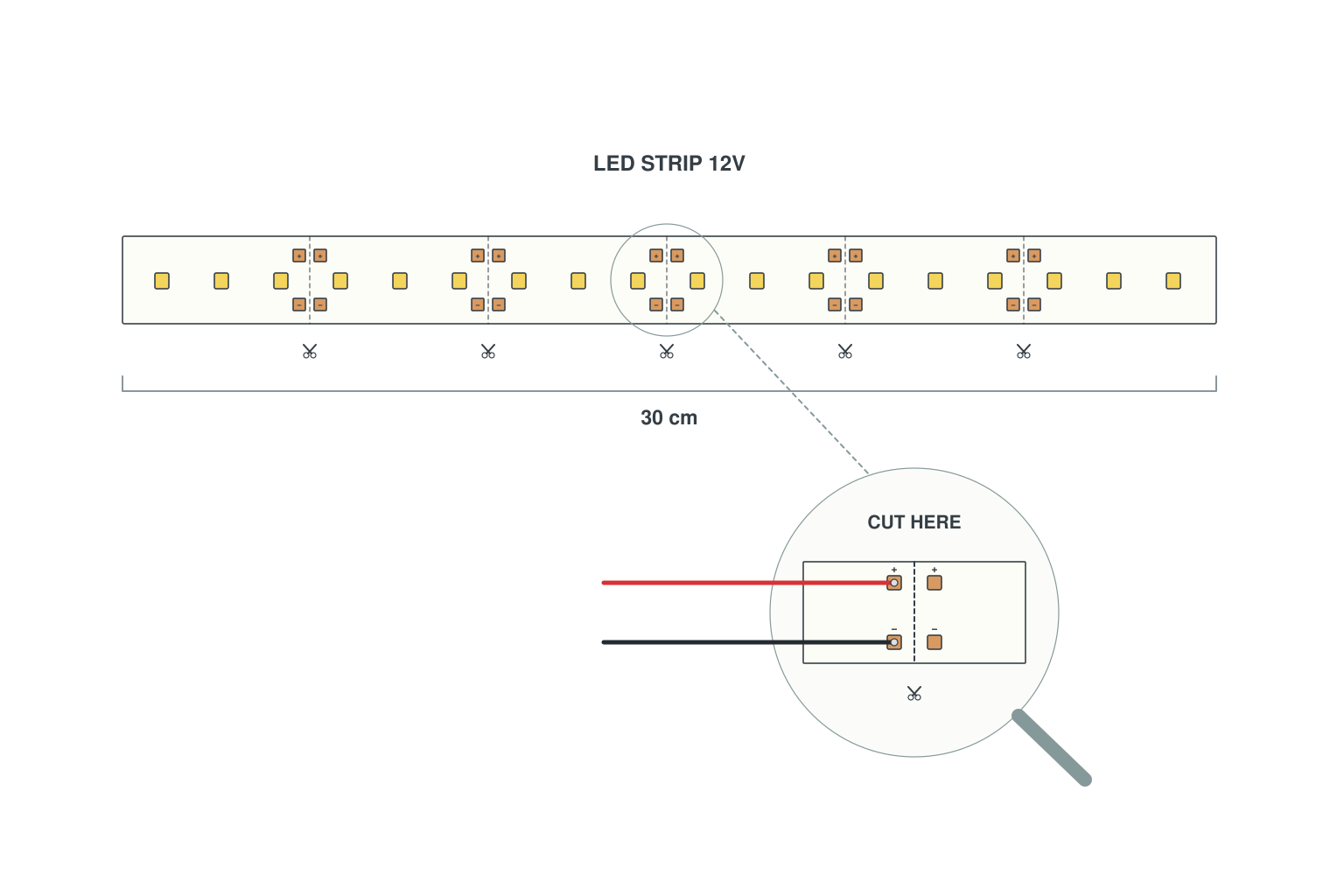
- Find the cut mark: a line with a scissors symbol every 3 LEDs (12 V) or 6 LEDs (24 V); only cut there.
- The copper pads either side of the line are the connection points. On a 2-pin strip they are marked + and -.
- Red wire to +, black wire to -. Reversed polarity does no harm but the strip stays dark.
- The arrow or "IN" mark on addressable LED strips shows signal direction; plain strips can be fed from either end.
Read more: Can you cut LED strips? · How to connect LED strip lights
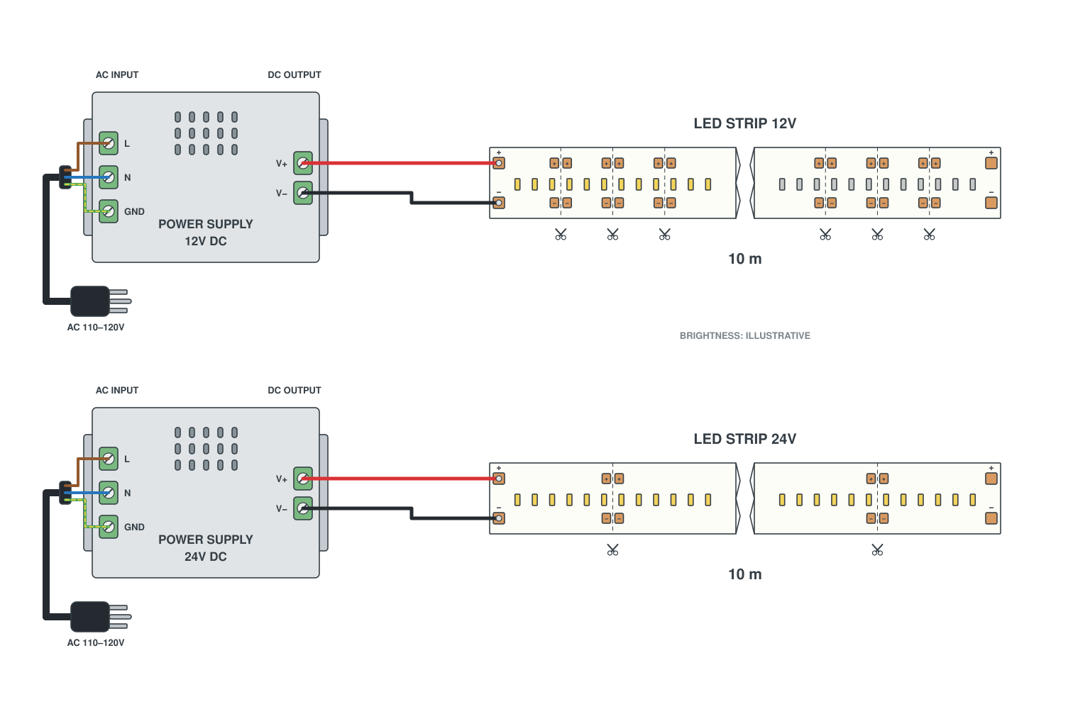
- At the same wattage a 24 V strip draws half the current, so the copper on the strip loses half the voltage and the far end stays bright.
- Rule of thumb from one feed point: 12 V up to 5 m, 24 V up to 10 m; beyond that add a feed point (see section 2).
- Everything on one circuit must be the same voltage: strip, controller and power supply.
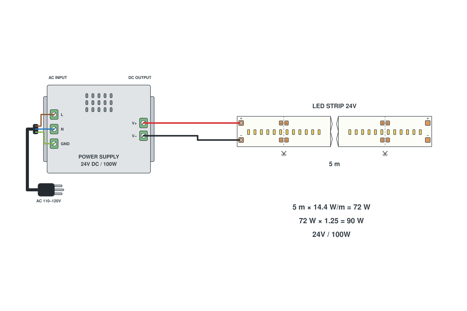
- Multiply the length by the watts per metre printed on the reel: 5 m x 14.4 W/m = 72 W.
- Add 20-30 % headroom so the supply is not running flat out: 72 W x 1.25 = 90 W, so choose a 100 W supply.
- Check the amps as well: 90 W / 24 V = 3.75 A. The controller and the wire must carry that current too.
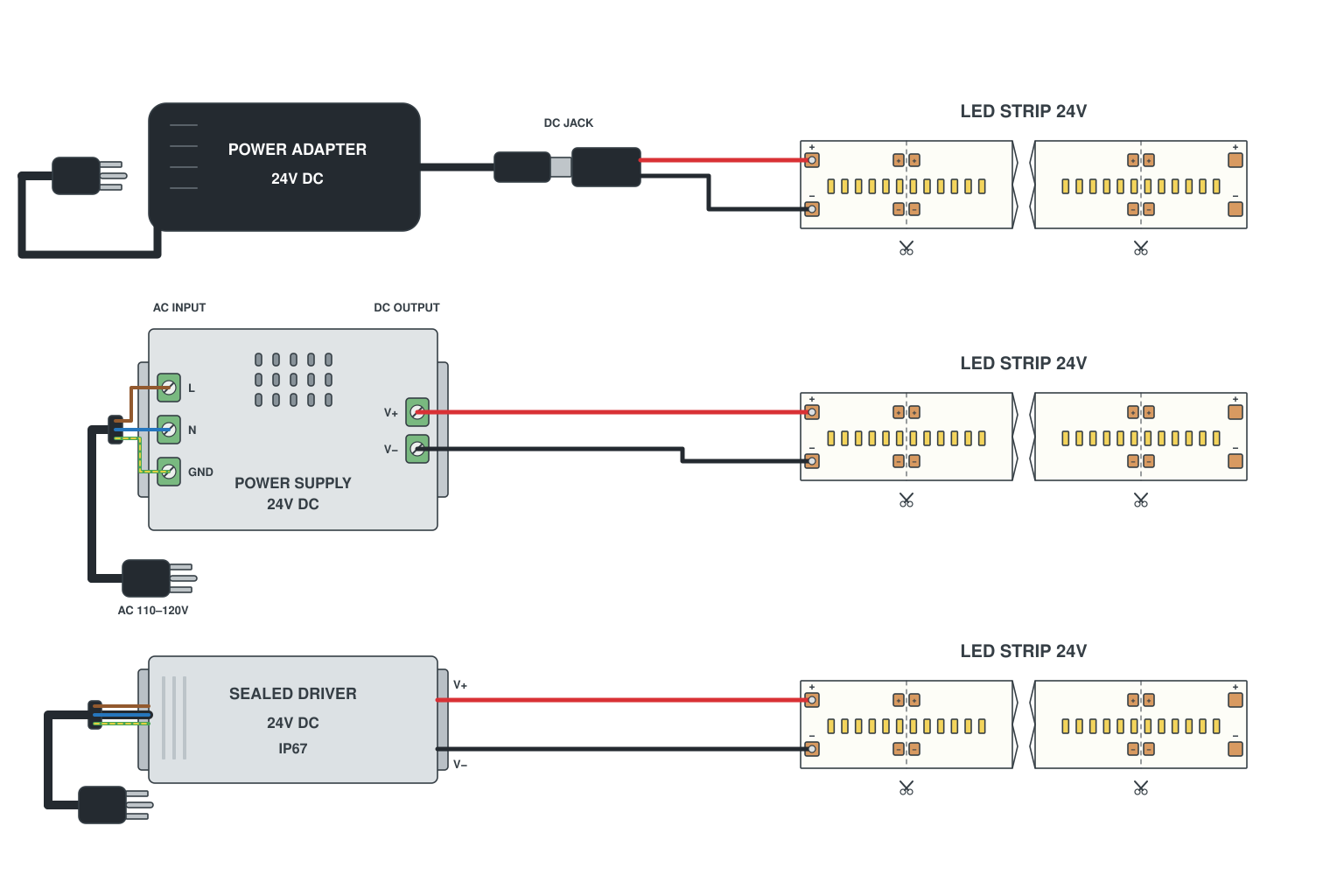
- Plug-in adapter (up to about 60 W): plugs into a socket, DC barrel jack on the other end, good for one 5 m strip.
- Enclosed metal supply (100-600 W): screw terminals, wire the mains L, N and earth yourself or have an electrician do it; put it in a ventilated cupboard.
- Waterproof driver (IP67): sealed cables both ends, for outdoors or damp rooms; no earth terminal needed but keep the plug end dry.
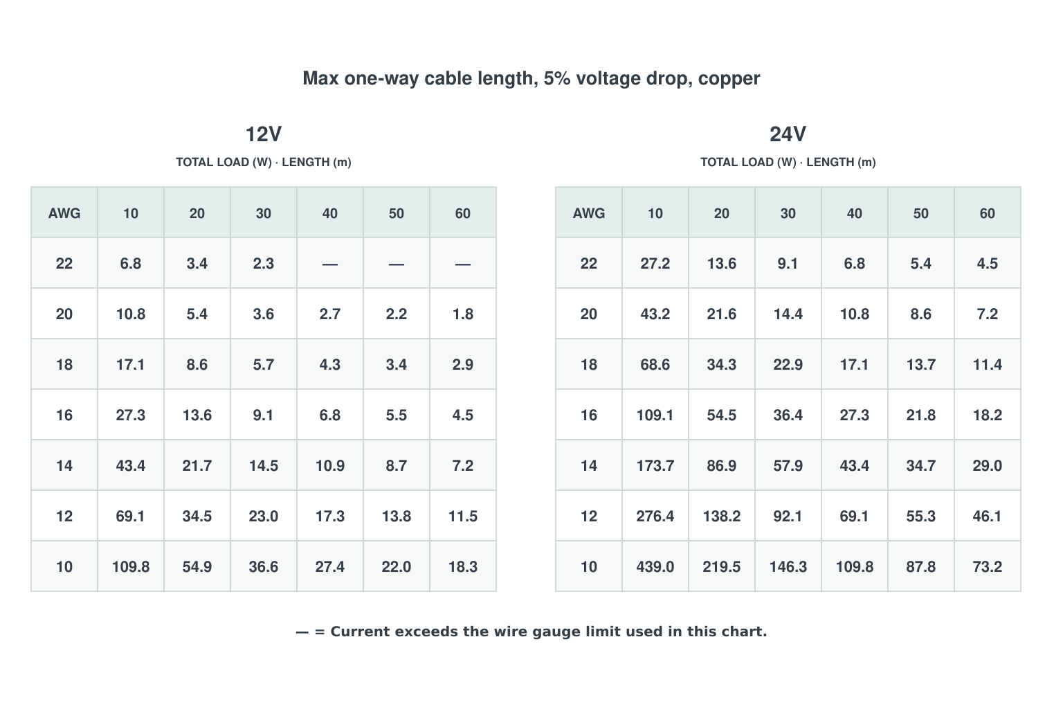
- The chart is for the feed cable from the power supply to the first pad of the strip (one-way length), not for the strip itself; strip length limits are in B2.
- Find the current: total strip watts divided by volts. 60 W at 12 V is 5 A, the same 60 W at 24 V is 2.5 A.
- Read the chart for that voltage: the cell is the longest cable on that gauge that keeps the drop inside 5 % of nominal (0.6 V at 12 V, 1.2 V at 24 V), copper, two conductors, 20 C.
- 24 V allows about four times the cable of 12 V at the same watts: half the current and twice the volts to spare. When in doubt go one gauge heavier.
- A dash means that gauge cannot carry the current safely at all, whatever the length: 22 AWG tops out around 3 A.
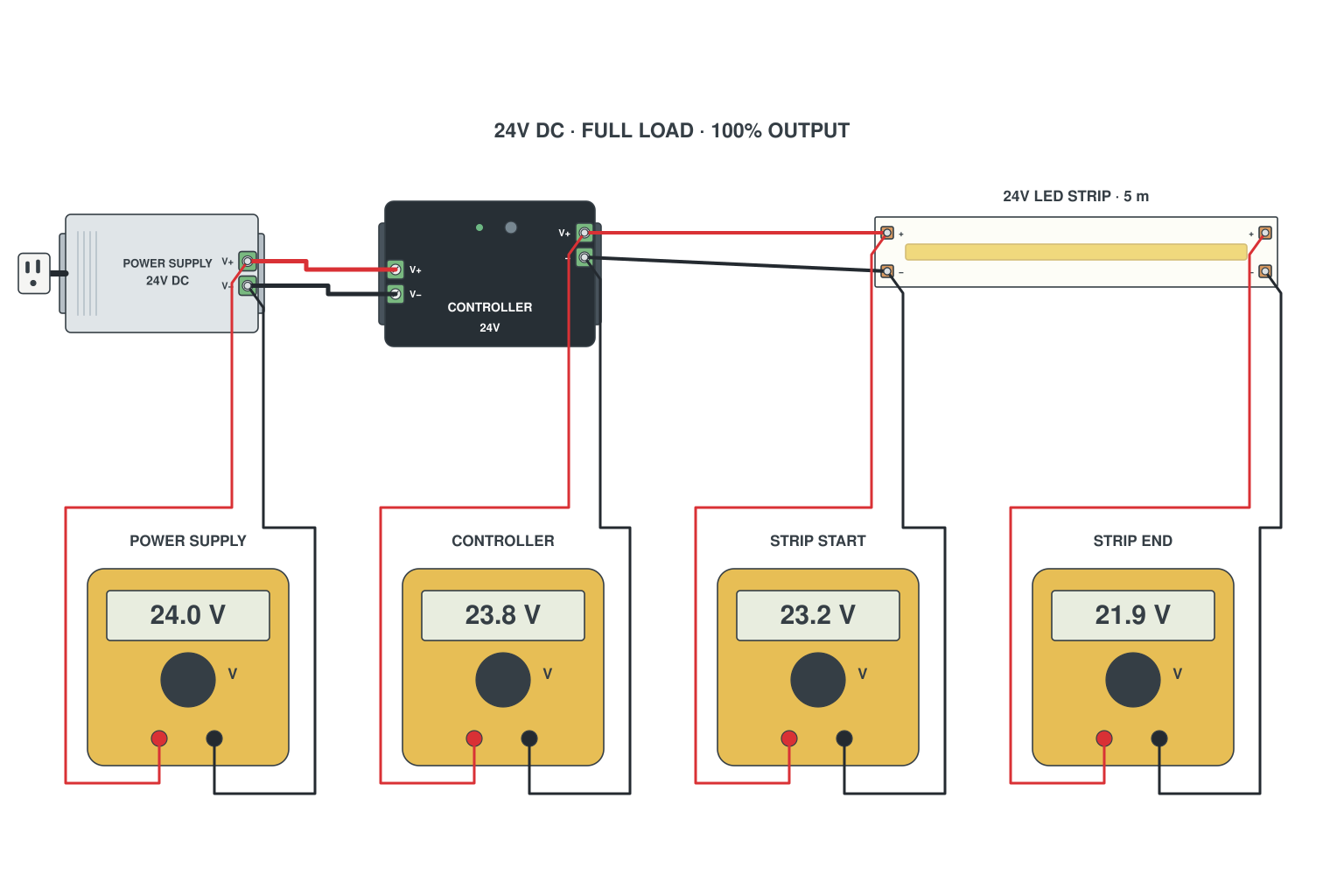
- Set the meter to DC volts and measure across V+ and V- at four points with the strip at full brightness: power supply output, controller output, LED strip start, LED strip end.
- Supply to controller start should lose almost nothing (24.0 to 23.8 V here). A bigger step means thin feed cable or a loose terminal.
- Controller to strip start (23.8 to 23.2 V) is the run cable: upsize the gauge or shorten it (see B5).
- Strip start to strip end (23.2 to 21.9 V) is the copper on the strip itself: that is normal, and a second feed at the far end fixes it.
Single colour LED strip wiring: 5 m, 10 m, 20 m, 50 m and 100 m
The same 2-wire LED strip, wired twelve different ways depending on the length and on where you can get a power cable to. This is the section we point most customers to first.
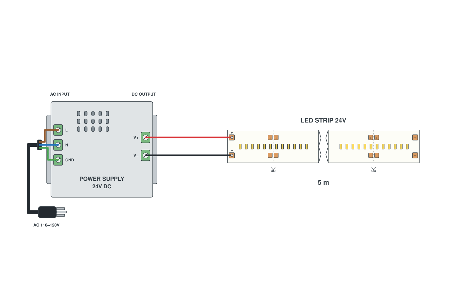
- Power supply output V+ to the strip + pad, V- to the - pad, using a 2-pin clip connector or solder.
- Plug the supply in only after the strip is connected; test, then stick the strip down.
- Add a dimmer between supply and strip if you want brightness control.
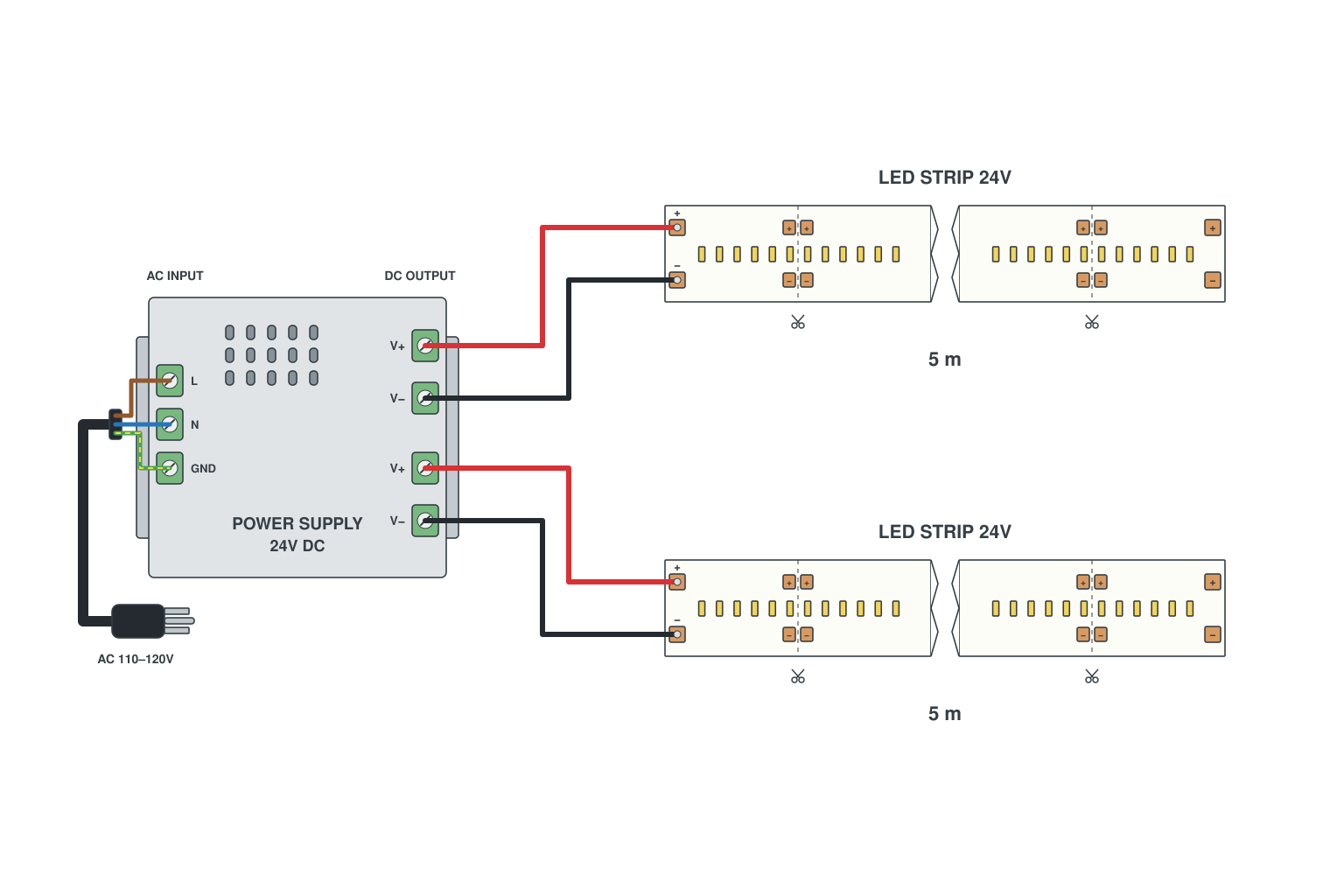
- Do not join the second reel to the end of the first: 10 m end-to-end at 12 V is dim at the far end.
- Run a separate pair of wires from the power supply terminals to the start of each reel (parallel).
- Size the supply for both reels: 2 x 72 W x 1.25 = 180 W.
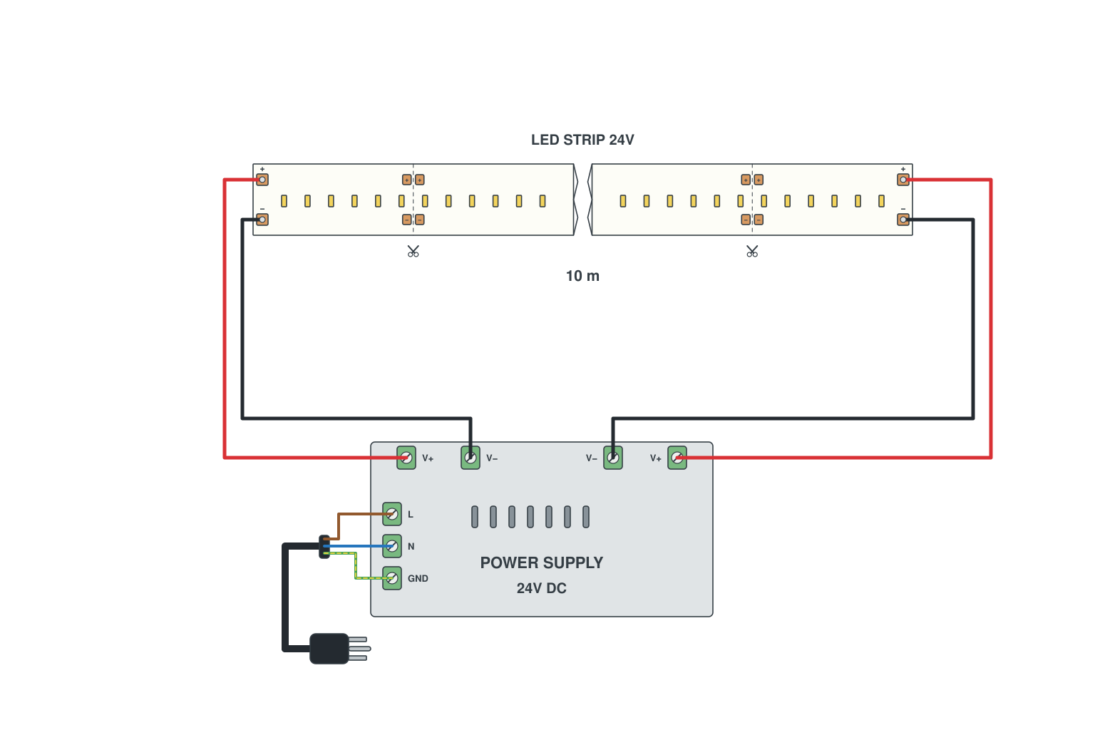
- Connect the supply to the start of the strip as usual.
- Run a second pair of wires (18 AWG or heavier) from the same supply terminals along the back of the strip to the far end and connect them there.
- Both ends now see full voltage, so the middle only drops half as much.
Read more: Why LED strips suffer voltage drop
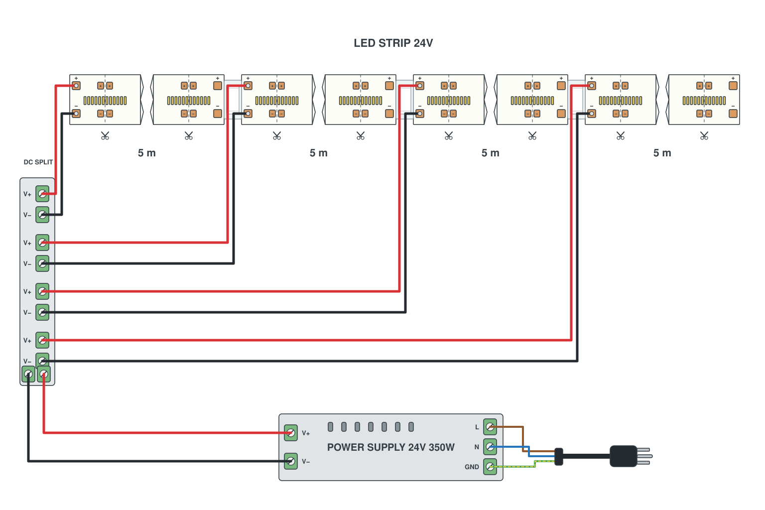
- Split the run into 5 m (12 V) or 10 m (24 V) sections; each section gets its own feed pair from the supply.
- One 24 V 300-350 W supply with four feed pairs, or two 150 W supplies each feeding two sections. Keep the supply near the middle to shorten the wires.
- Join the sections physically with a connector so the light is continuous, but keep the feeds separate.
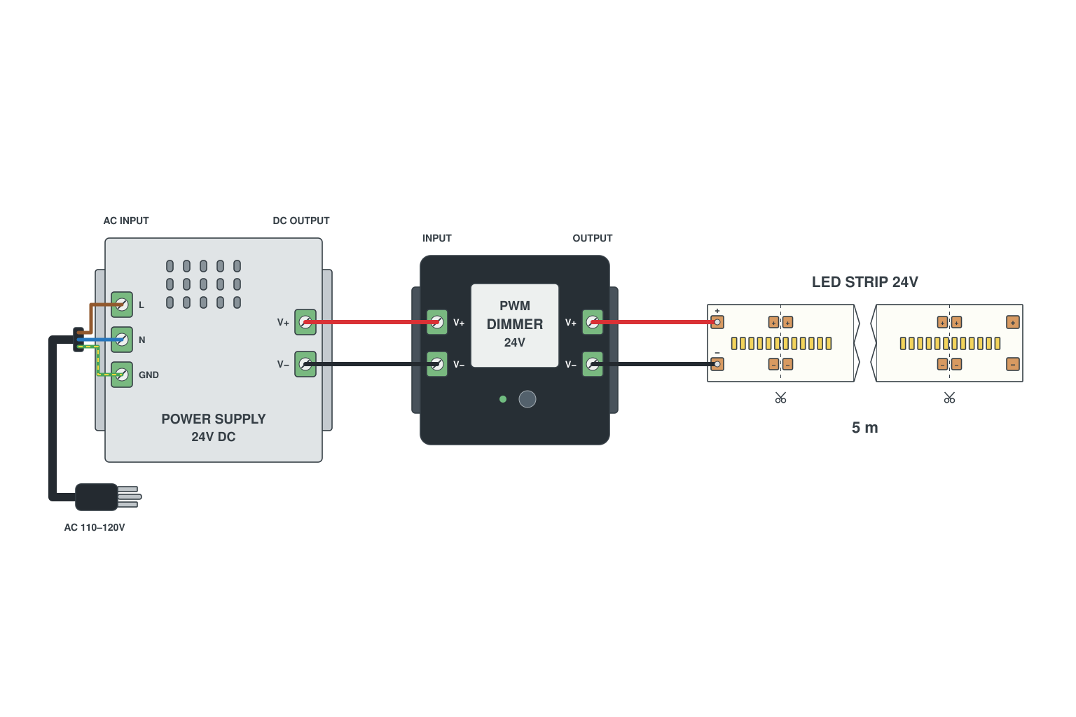
- Supply output into the dimmer IN terminals, strip on the OUT terminals; polarity marked on the box.
- RF remote, wall panel or push switch pairs with the dimmer; nothing changes at the strip.
- The dimmer amps must cover the strip current (a 5 m 72 W 24 V strip is 3 A; most dimmers are 8-30 A).
Read more: How to wire single colour LED strips
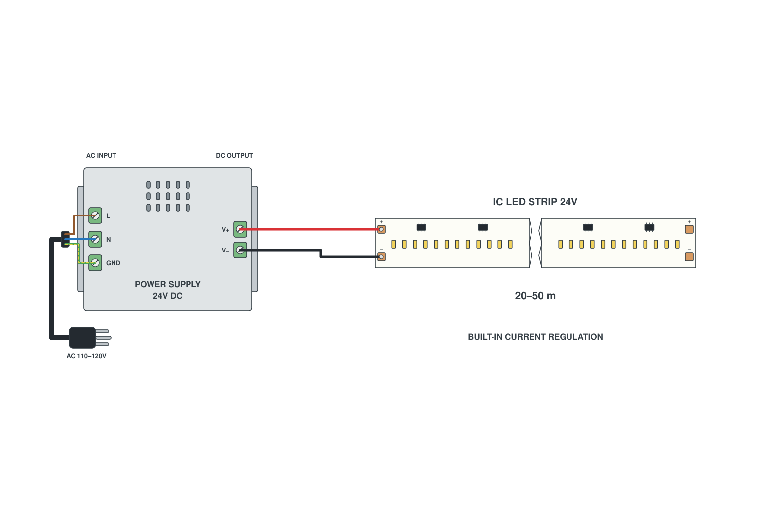
- Use a constant-current (built-in IC) strip: the driver on the strip keeps each section at the same brightness regardless of the length.
- One feed point at the start; 24 V; supply sized for the whole length.
- Cut marks are further apart (typically every 10-20 cm) so plan the end point.
Read more: Long strips without voltage drop
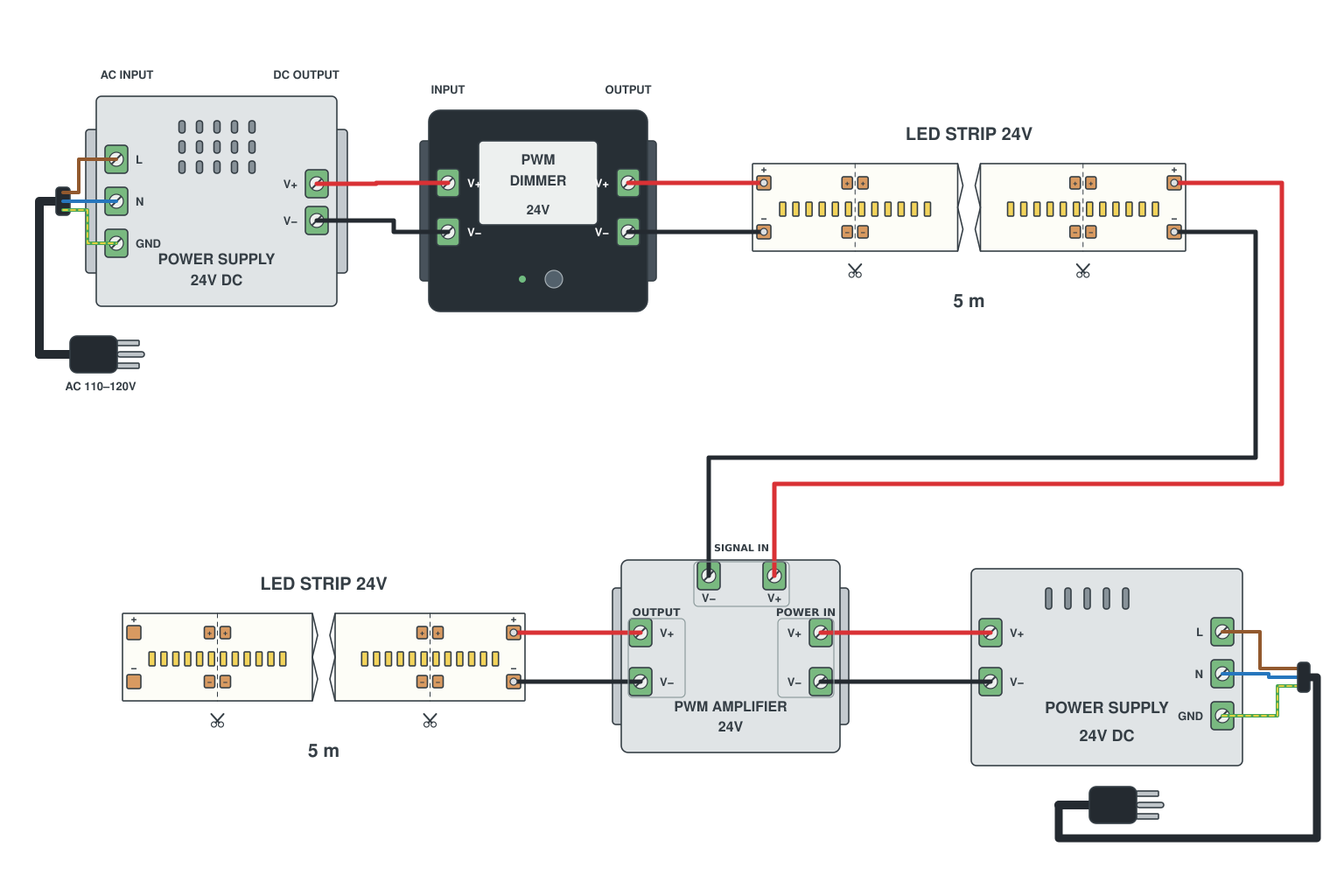
- Dimmer feeds strip 1 as normal.
- At the end of strip 1 connect an amplifier: its IN takes the dimmed signal from strip 1, its OUT feeds strip 2.
- The amplifier needs its own power supply input (V+/V-) so the current for strip 2 does not pass through strip 1.
Read more: How to wire single colour LED strips
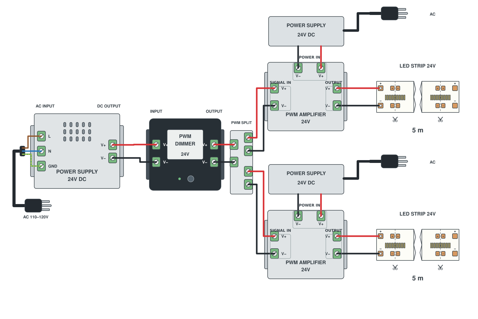
- Dimmer output goes to the signal input of each amplifier in parallel (thin wire is fine, it carries no load).
- Each amplifier gets its own supply and drives its own strip.
- All branches follow the dimmer at once; add more amplifiers as needed.
Read more: How to wire single colour LED strips
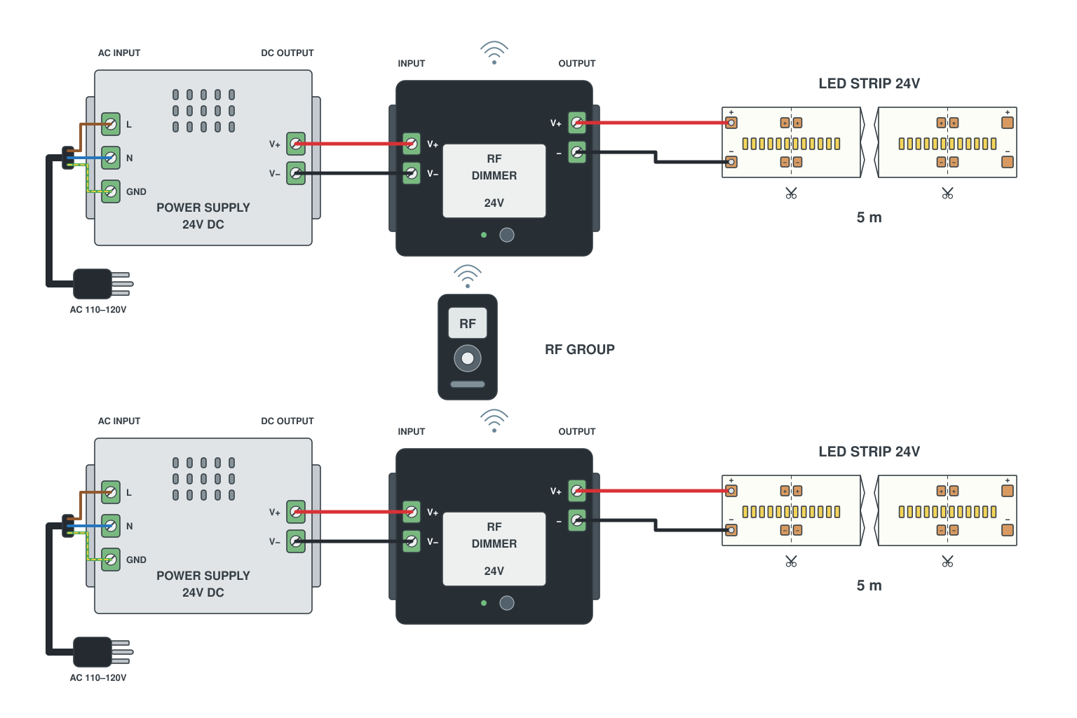
- Each run gets a small RF dimmer receiver and its own supply, wired like S5.
- Pair every receiver to the same remote or wall panel; they respond together.
- Nothing is wired between the receivers; the RF link replaces the signal cable.
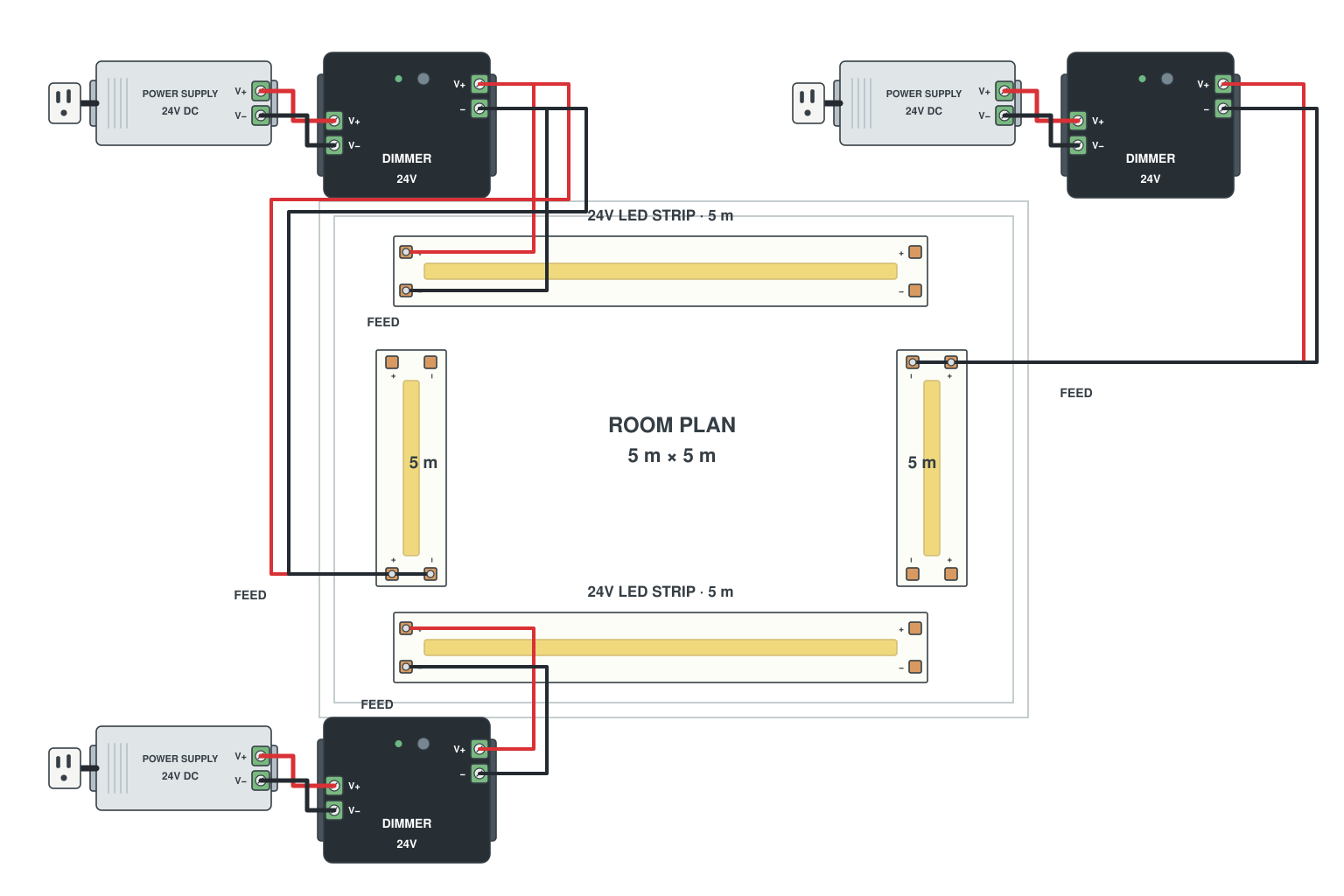
- Draw the perimeter and mark where the mains sockets are.
- Split the strip into runs of 5 m (12 V) or 10 m (24 V); place a supply and dimmer near the middle of each run.
- Add the cable lengths to the plan and check them against the wire chart (B5).
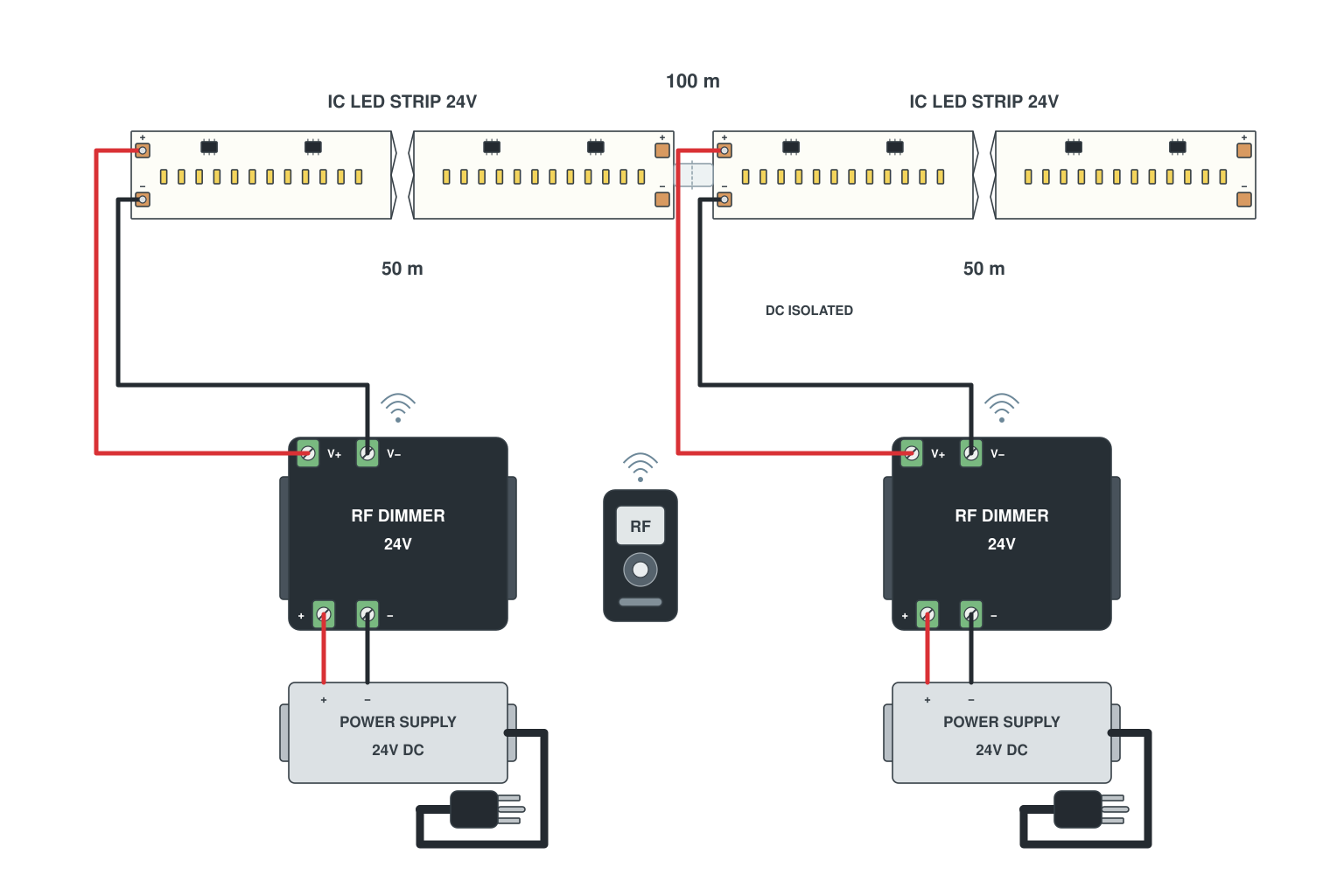
- Use constant-current LED strip in 50 m sections; each section is fed once from its own 24 V supply.
- Join the sections physically so the light is continuous.
- One RF remote paired to all receivers switches the whole corridor.
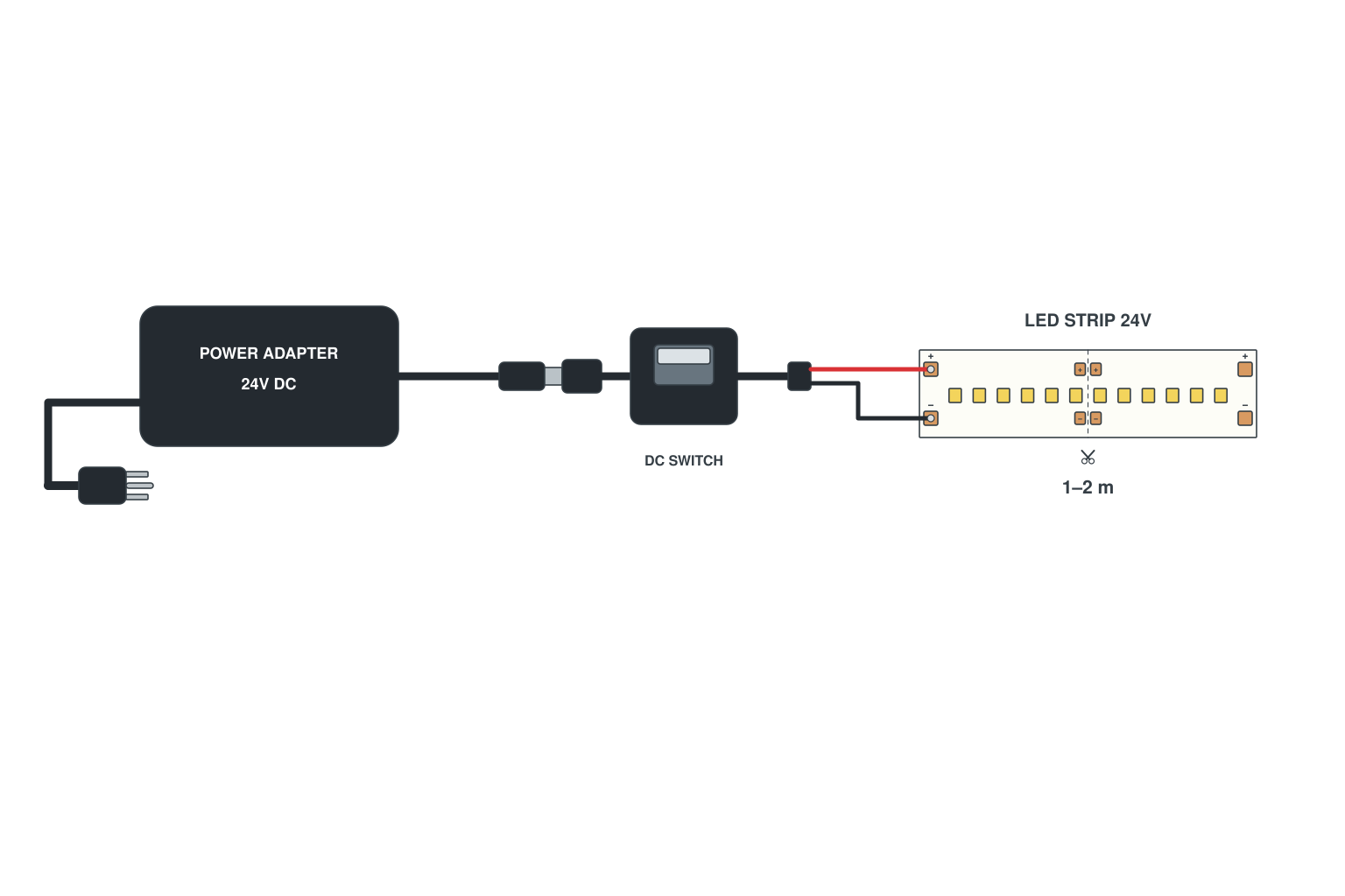
- Cut the strip to length at a cut mark; solder or clip a DC barrel jack lead to it.
- Plug the lead into a 12 V or 24 V plug-in adapter; an inline switch or a mini dimmer goes between.
- Adapters up to 60 W cover about 4 m of standard strip.
Read more: How to connect LED strip to a power supply
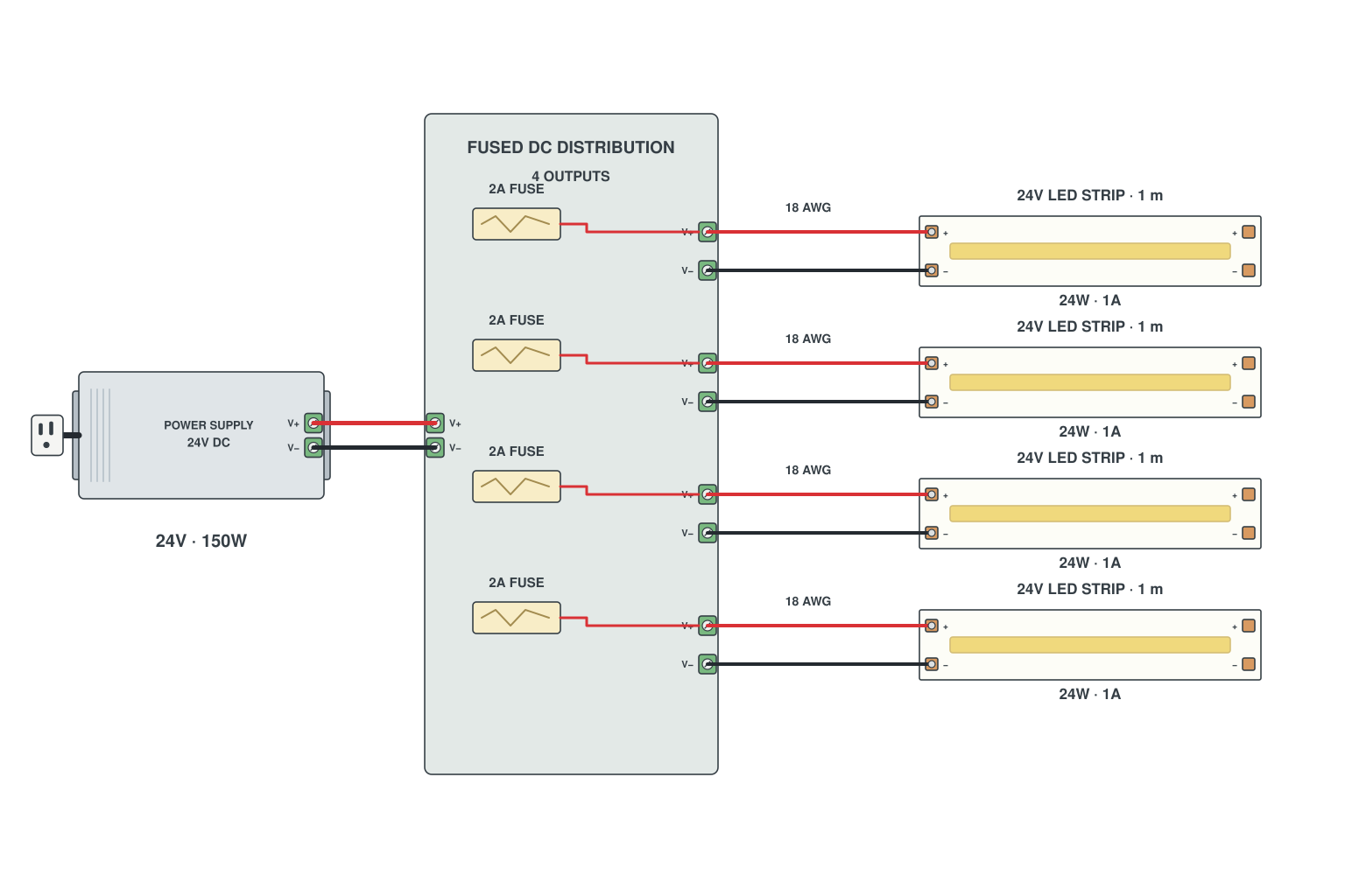
- Wire the supply V+ and V- into a DC distribution block that has one fuse per output.
- Fuse each output at about twice the run current: a 24 W run at 24 V draws 1 A, so a 2 A fuse.
- Run a separate 18 AWG pair from each fused output to the start of its LED strip; never daisy-chain the runs off one fuse.
- Size the supply for the total: four 24 W runs = 96 W, so a 150 W supply leaves headroom.
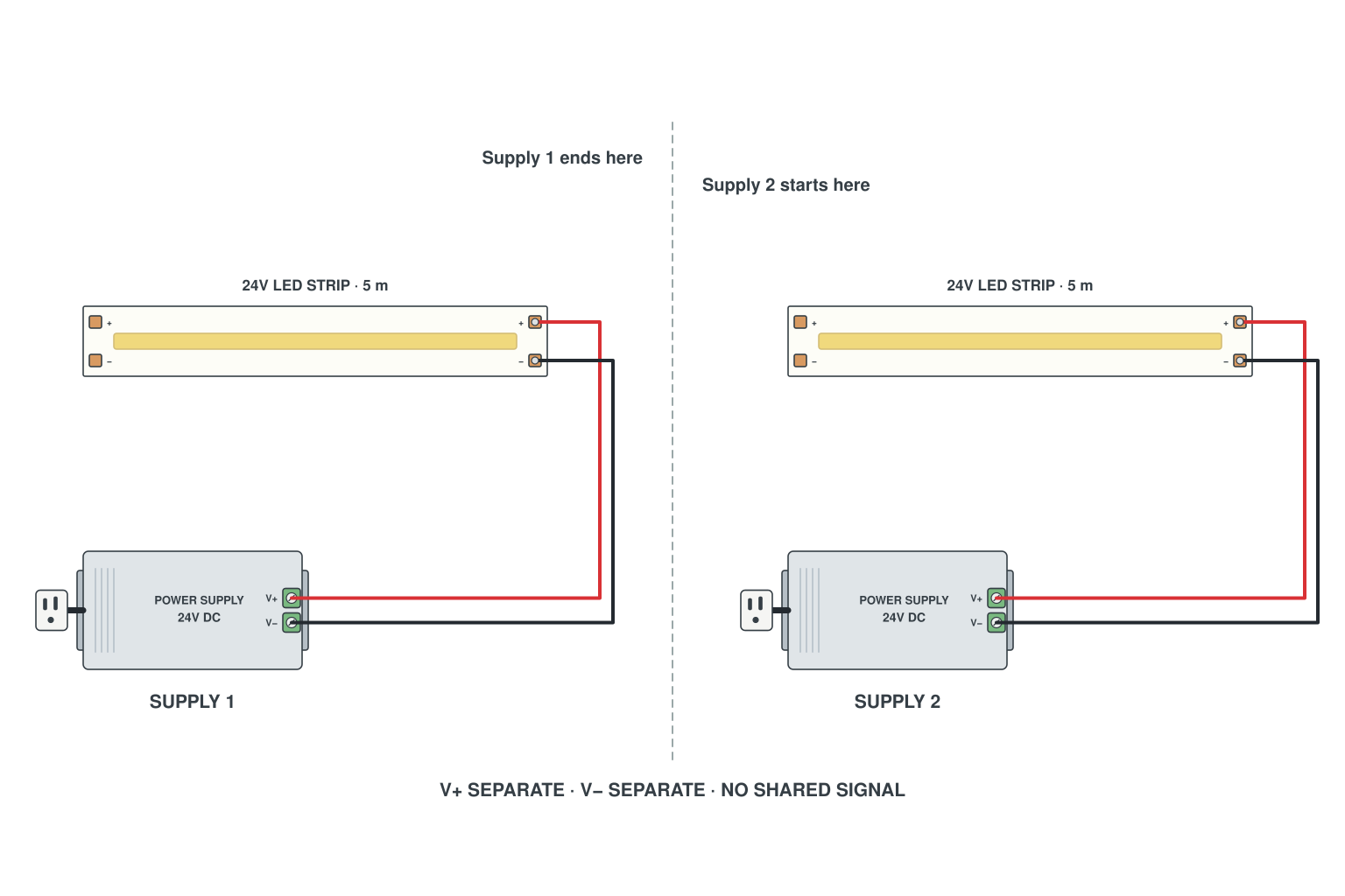
- Cut the run at a cut mark where the first supply reaches its limit; the second section gets its own supply.
- Supply 1 V+ and V- to section 1 only, supply 2 to section 2 only. Do not join the two V+ lines and do not join the two V- lines.
- Mains side both supplies can share the same circuit; the DC sides stay separate.
Tunable white (CCT) LED strip wiring
Three pads instead of two, a CCT controller, and what changes when the run gets long or when you want two rooms on one remote.
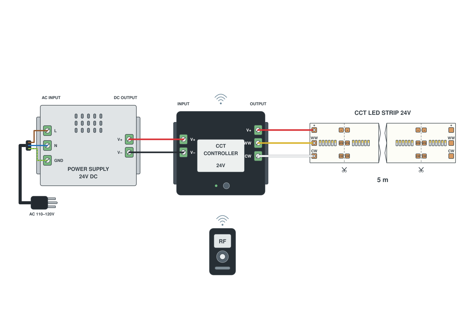
- Supply into the CCT controller; controller outputs V+, WW and CW to the three pads (order printed on the strip).
- V+ is common; the controller mixes warm and cool by varying the two negative channels.
- Pair the remote or wall panel; set 2700-6500 K and brightness from there.
Read more: How to wire tunable white LED strips
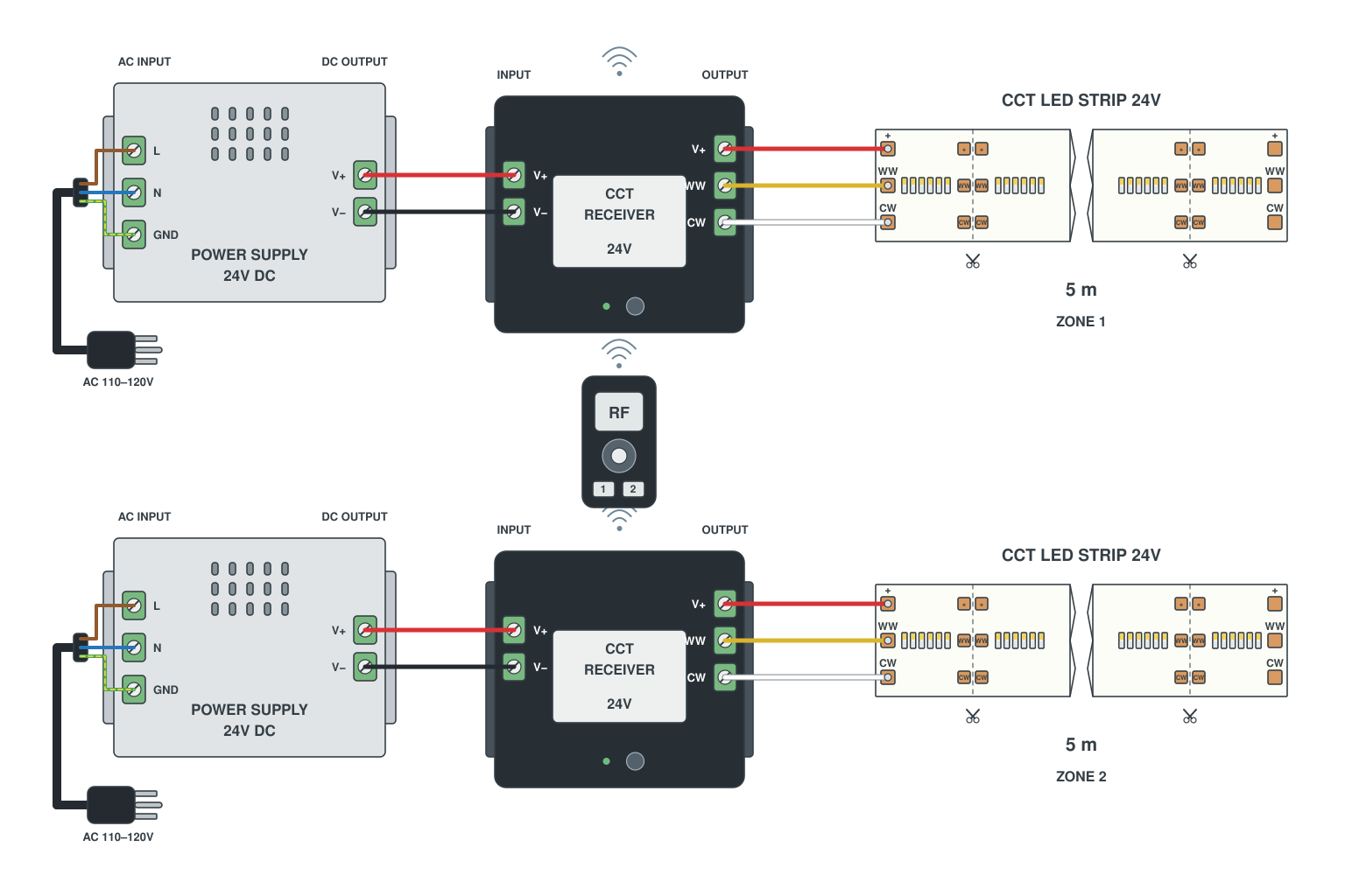
- Each strip gets its own CCT controller and supply, wired as in T1.
- Pair both controllers to one multi-zone remote: zone 1 and zone 2 on the remote, or link them so they act together.
- No wire runs between the two zones; the link is RF.
Read more: How to wire tunable white LED strips
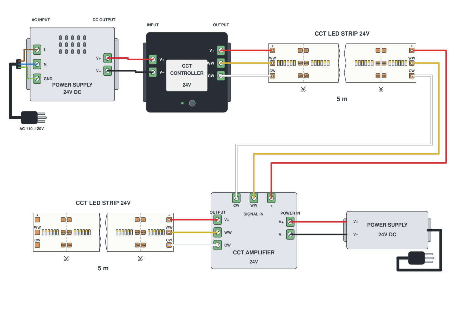
- Controller drives the first reel.
- At the end of reel 1 add a 3-channel (WW/CW) amplifier with its own supply; its output feeds reel 2.
- Repeat every reel; the colour temperature stays in step all along the chain.
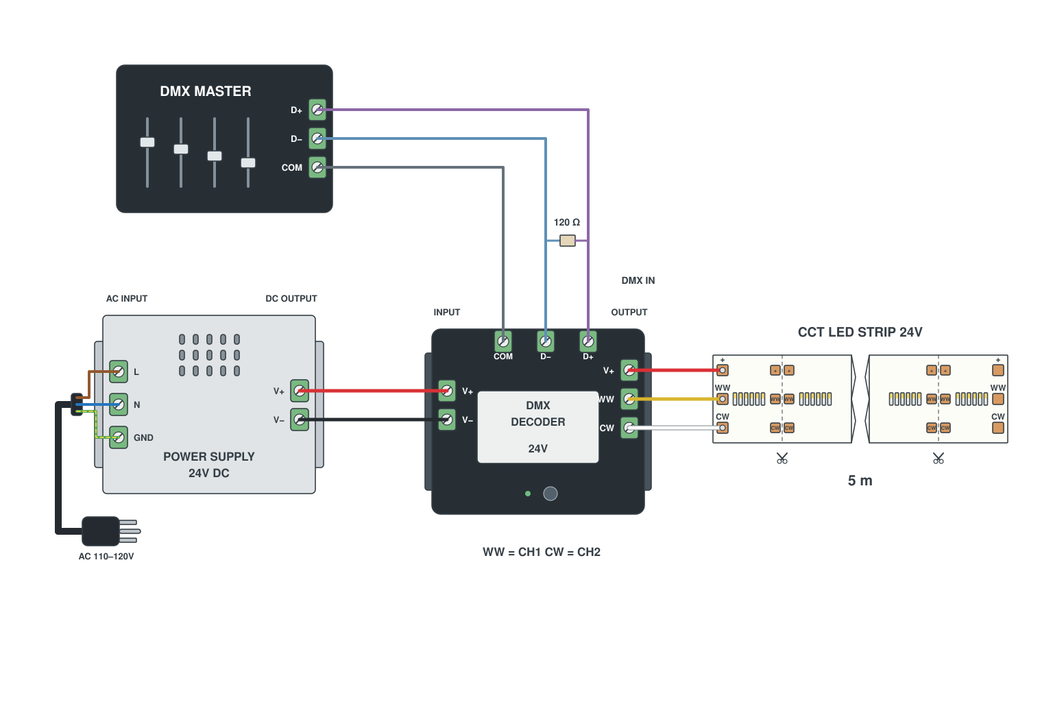
- DMX master or console into a 2-channel DMX decoder.
- Decoder outputs WW and CW to the CCT LED strip; 24 V supply into the decoder.
- Assign two DMX channels: one for warm, one for cool; mix them from the desk.
RGB, RGBW and RGB+CCT LED strip wiring
Controller pinouts, running two reels off one controller, and where the amplifiers go on runs of 10 to 50 m. The mistakes here are almost always a wrong pad order or a controller with too few channels.
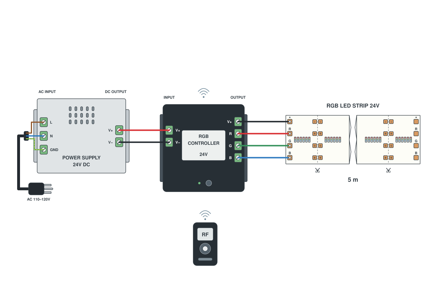
- Supply into the RGB controller (V+/V-).
- Controller outputs V+, R, G, B to the four pads, in the order printed on the strip; a 4-pin clip connector keeps the colours straight.
- Pair the remote, test all three colours, then stick the strip down.
Read more: How to wire RGB LED strips
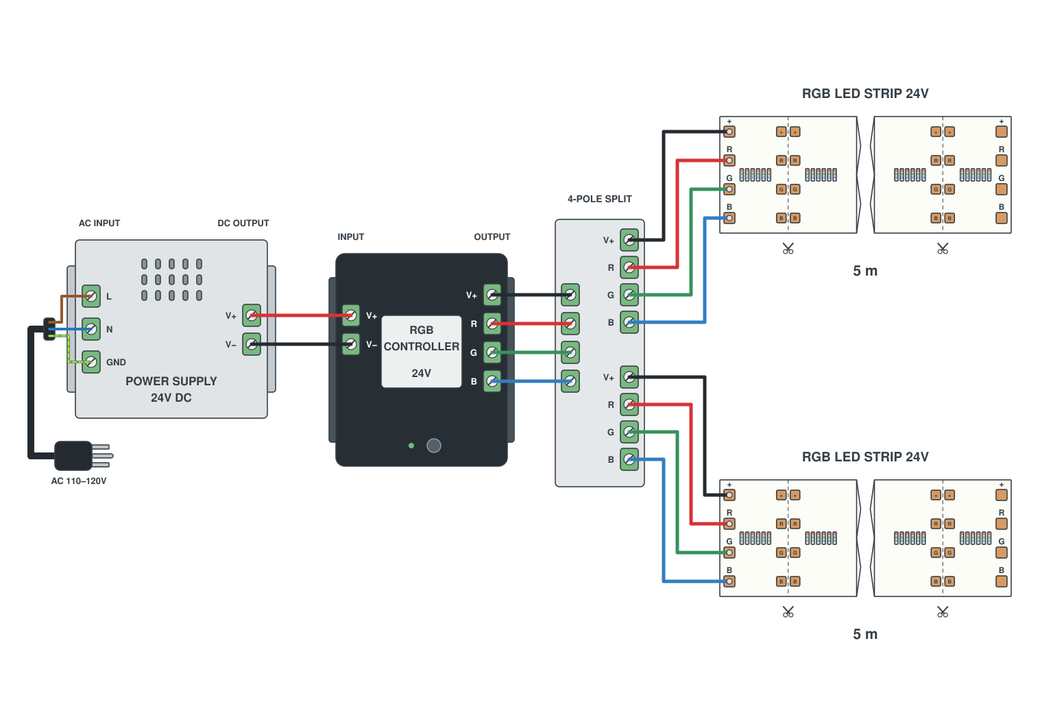
- Wire both reels to the controller output in parallel (a 4-wire splitter cable, or two cables to the same terminals).
- Check the controller rating: 2 x 5 m of 14.4 W/m at 24 V is 6 A total, 2 A per channel; most controllers are 6 A per channel.
- Size the supply for both reels plus headroom.
Read more: How to wire RGB LED strips · Why LED strips suffer voltage drop
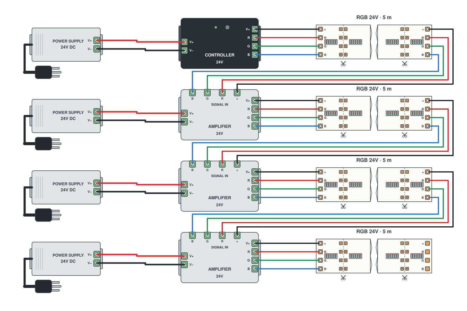
- Controller feeds the first 5-10 m.
- At the end of that section connect an RGB amplifier: IN from the strip, OUT to the next section, plus its own supply.
- Repeat every 5-10 m; the colour signal passes down the chain, the power comes in locally so nothing dims.
Read more: How to wire RGB LED strips
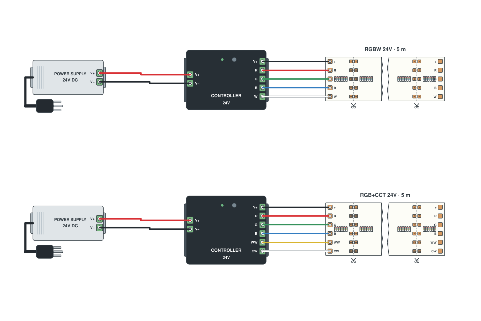
- RGBW: controller outputs V+, R, G, B, W to a 5-pad strip. Use a 5-pin connector.
- RGB+CCT: outputs V+, R, G, B, CW, WW to a 6-pad strip. Use a 6-pin connector.
- Both use one common V+; every other pad is a switched negative channel. Match the controller to the pad count, not just the colour name.
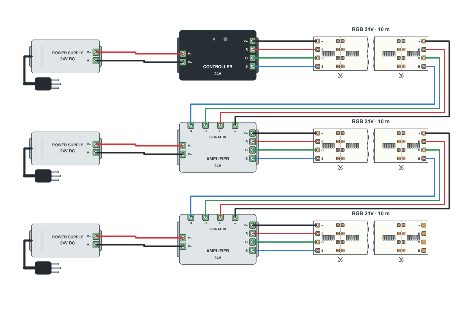
- Divide the perimeter into 10 m segments; each segment has its own 24 V supply and an amplifier at its start.
- One master controller at the first segment; the signal daisy-chains through the amplifiers.
- All supplies share the mains circuit; the DC sides stay separate except for the signal wire and V+ reference.
Read more: How to wire RGB LED strips
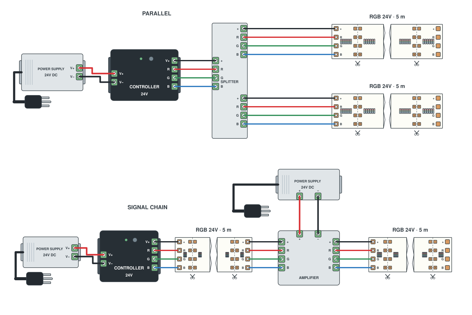
- Total length up to 10 m and all reels start near the controller: parallel wiring, no amplifier.
- Any reel that starts more than 3-4 m from the controller, or total length above 10 m: amplifier at that reel.
- Amplifier plus local supply is also the answer when the controller is rated too low for the total current.
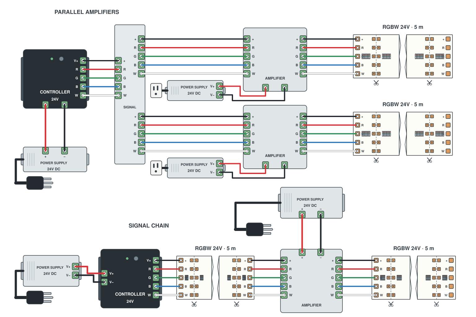
- Series: controller -> reel 1 -> 4-channel amplifier -> reel 2, each amplifier with its own supply.
- Parallel: controller signal to several amplifiers side by side, each with a supply and a reel.
- Either way the colours stay synchronised; only the power is local.
Read more: How to wire RGBW LED strips
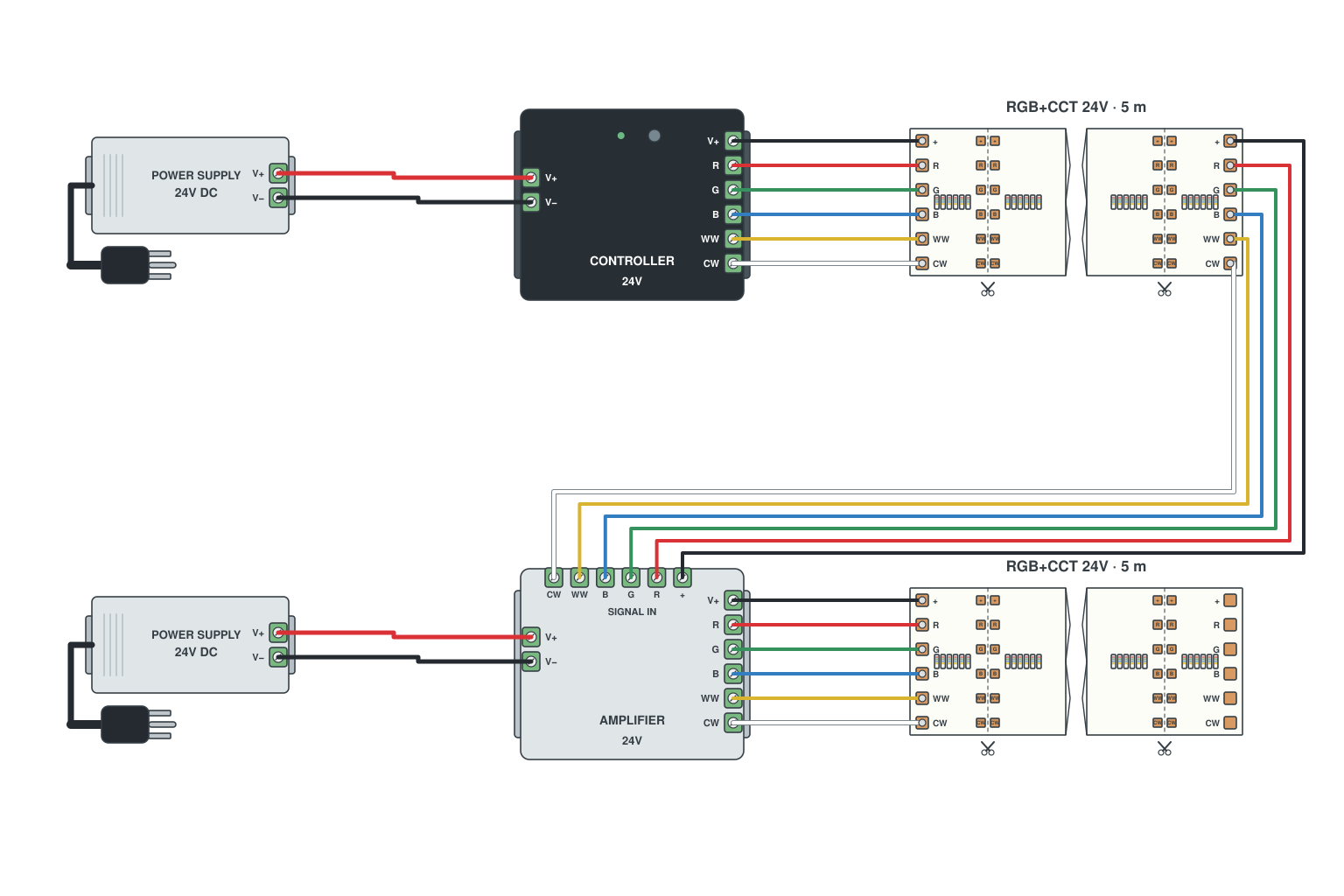
- Controller -> 5 m strip -> 6-channel amplifier (V+, R, G, B, CW, WW) -> next 5 m strip.
- Each amplifier takes its own 24 V supply.
- Keep the six wires in pad order at every joint; a 6-pin clip connector helps.
Read more: How to wire RGB+CCT LED strips
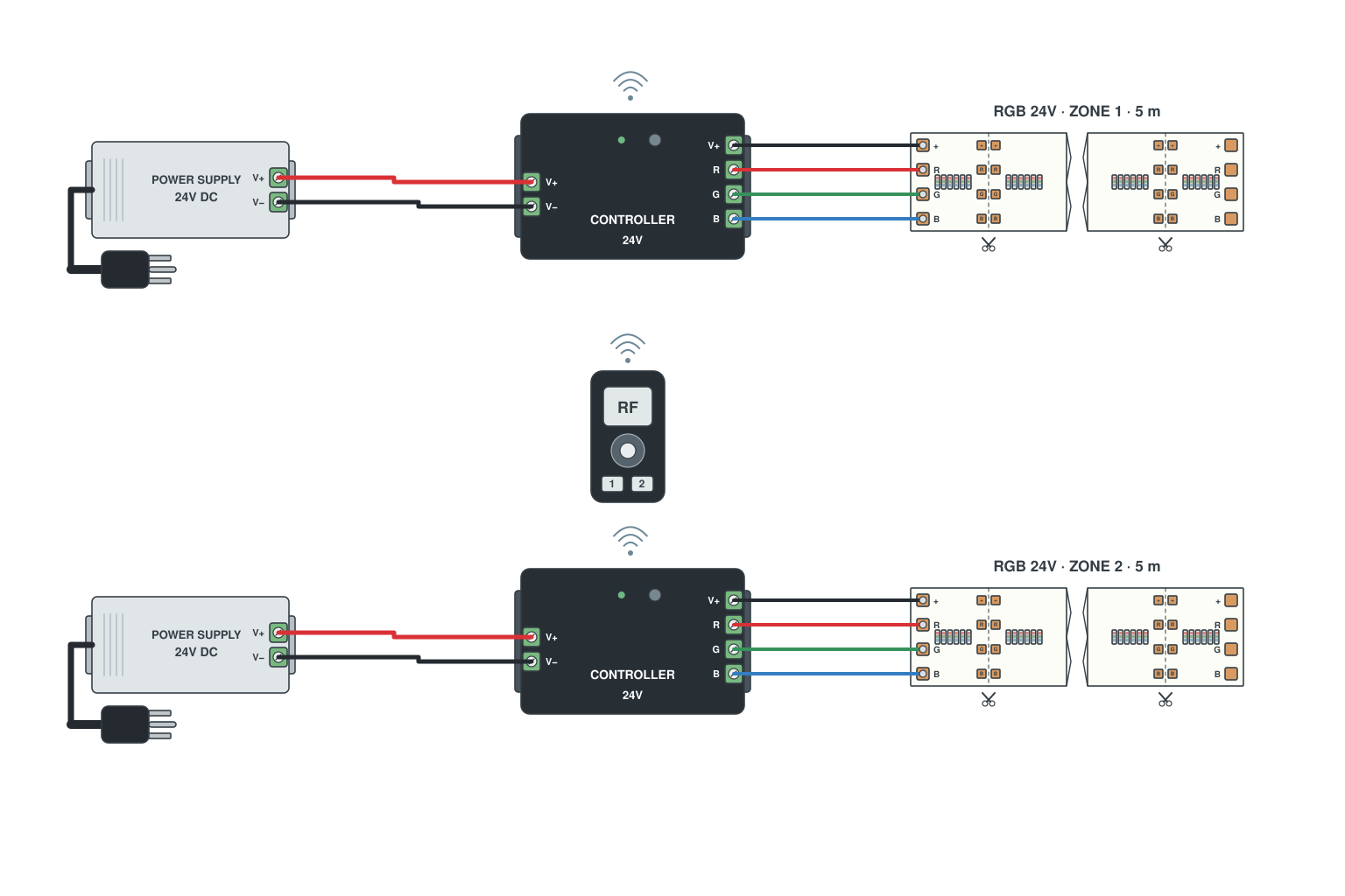
- Each strip gets its own RGB receiver and supply.
- Pair both receivers to one multi-zone remote as zone 1 and zone 2.
- No wire between the two; the remote addresses each zone or all zones.
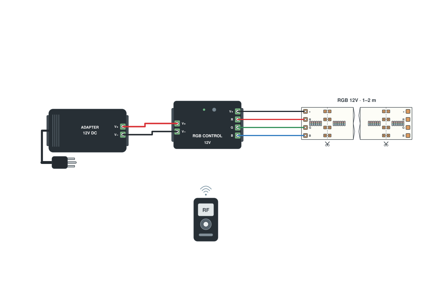
- Cut the strip at a cut mark; use a 4-pin clip to the mini controller lead.
- Mini controller into a 12 V plug-in adapter.
- IR or RF remote pairs to the controller.
Read more: How to wire RGB LED strips

- Take the injection feed from the RGB controller output terminals: V+, R, G and B, four wires.
- Land them on the matching pads mid-strip or at the far end so that section still follows the controller.
- Never connect the power supply V- straight to an R, G or B pad: that bypasses the controller PWM and locks the channel fully on.
- Injecting only the common V+ from the supply is fine on its own, but it does not fix dim colours; the channel lines need injecting too.
Read more: How to wire RGB LED strips · Why LED strips suffer voltage drop
Addressable (pixel) LED strip wiring: single signal, dual signal, breakpoint resume
Data direction, power injection, 5 V versus 24 V, the three signal types and how to keep a common ground. Half of the wiring questions we get are about this section, so it is the longest.
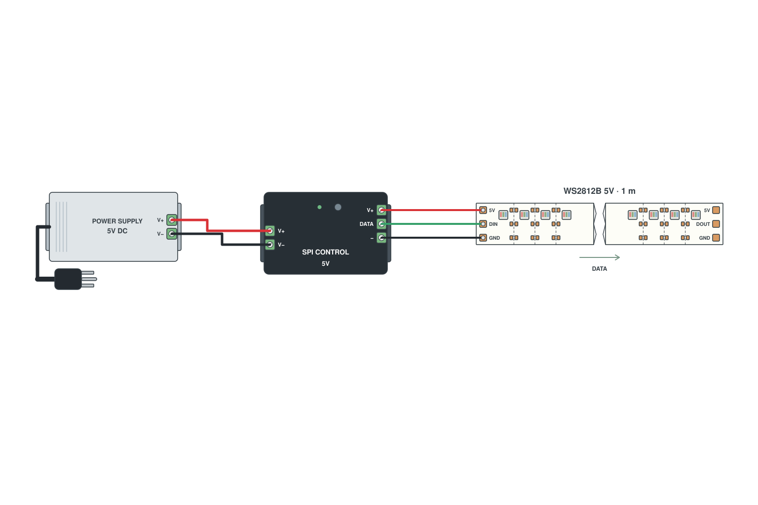
- Controller DATA (DO) to the strip DIN pad, controller GND to strip GND; the strip V+ can come from the controller or straight from the supply.
- Feed the strip at the end marked IN or with the arrow pointing away from you; data only travels one way.
- Keep the data wire short (under 1-2 m) or use a signal amplifier.
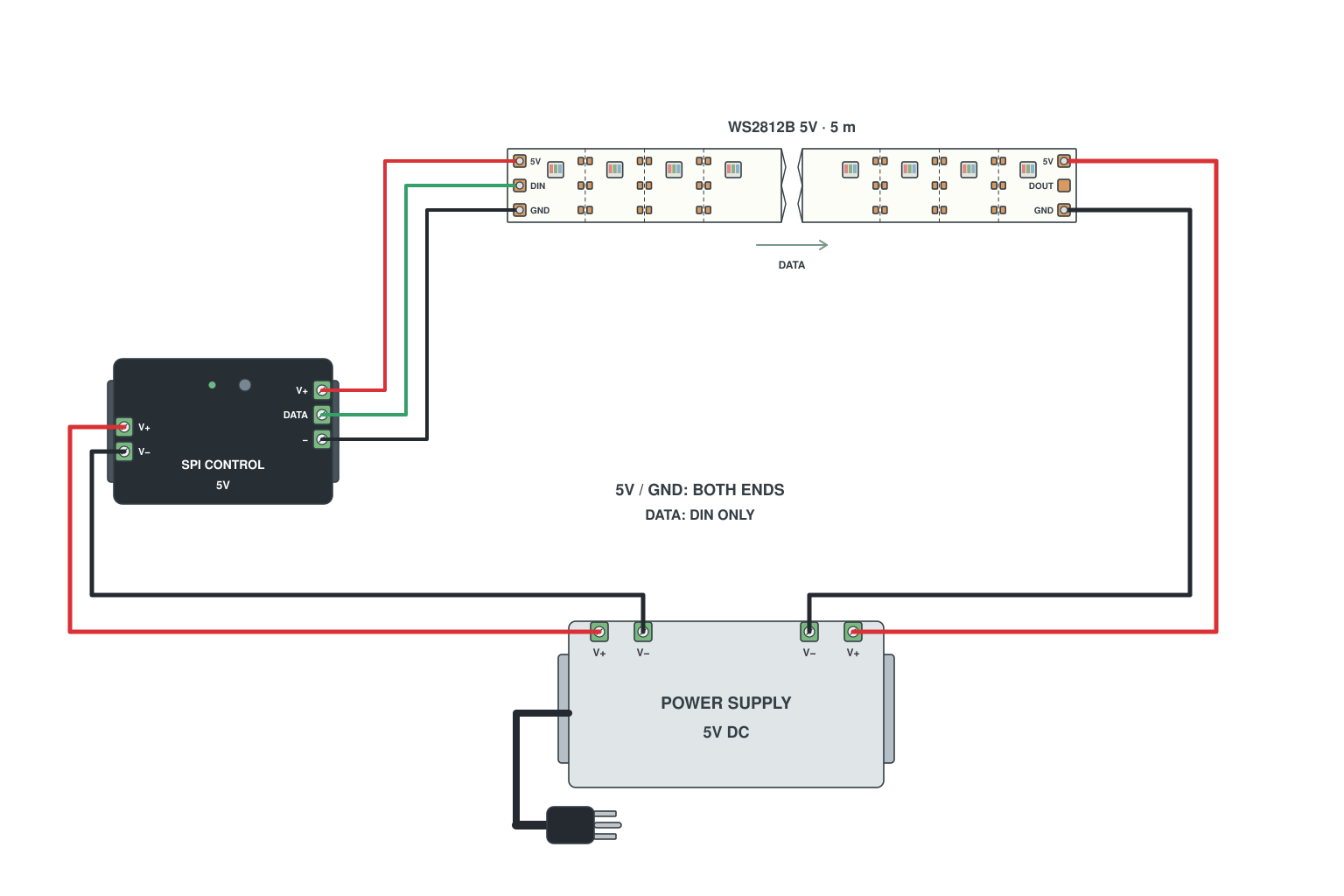
- Feed V+ and GND at the start as usual.
- Run a second pair of wires from the supply to the far end of the strip and connect them to V+ and GND there.
- Data still enters only at the start. Use 18 AWG or heavier for the injection wires.
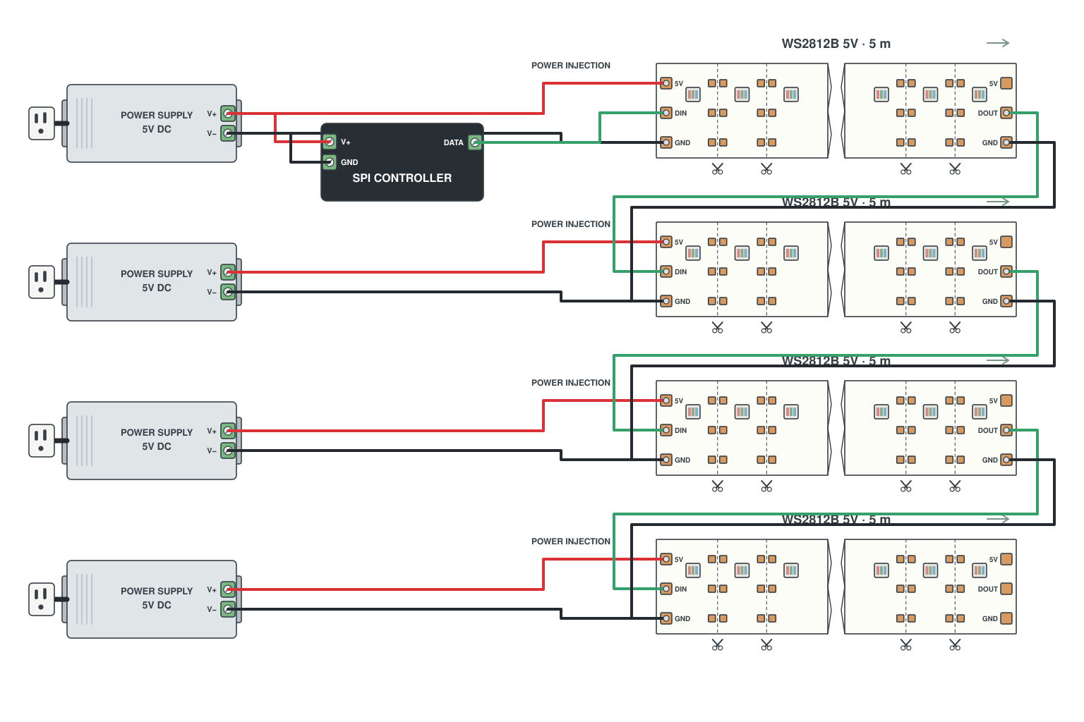
- Chain the reels for data: DOUT of reel 1 to DIN of reel 2, with GND.
- Give every 5 m reel its own V+/GND pair from the supply (or a supply per reel). Do not pass power through the reels.
- All GNDs, including the controller GND, must be joined.
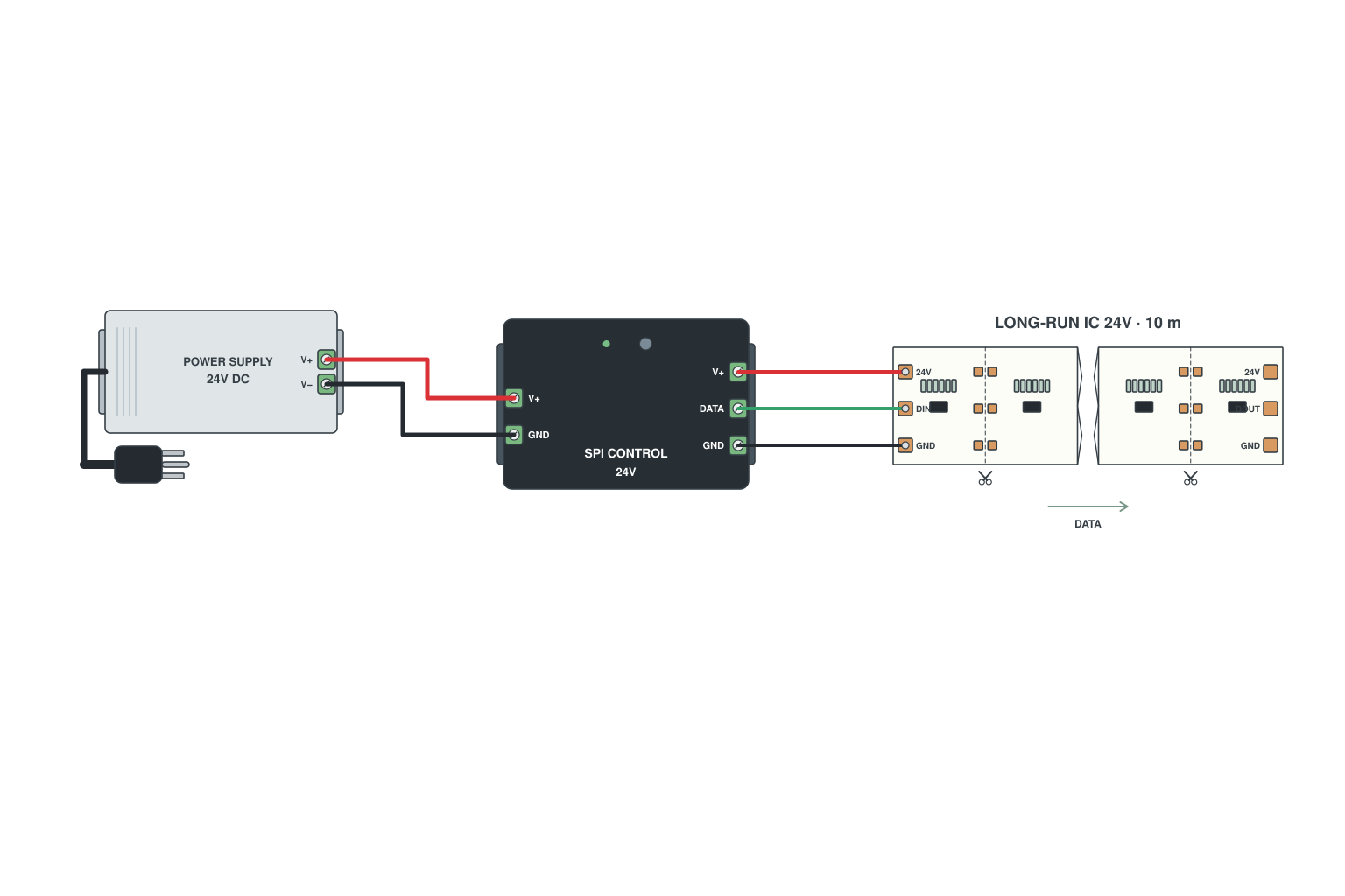
- Choose a 24 V addressable LED strip (WS2815-24, or a 24 V IC strip): one feed point covers 10-20 m.
- Wire it like A1: DATA and GND from the controller, V+ from the supply.
- WS2815 has a backup data pad (BI); connect it in parallel with DI so one dead pixel does not stop the chain.
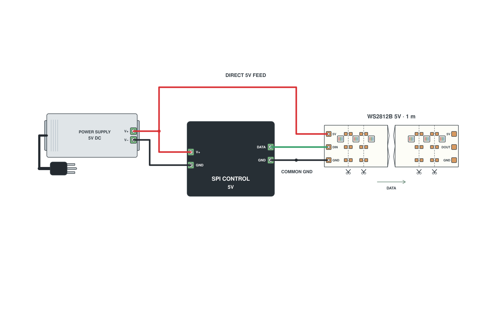
- Supply V+ and GND into the controller power input.
- Controller DATA and GND to the strip; strip V+ from the supply (through the controller only if it is rated for the current).
- The GND wire must be common to the supply, the controller and the strip: three GNDs joined.
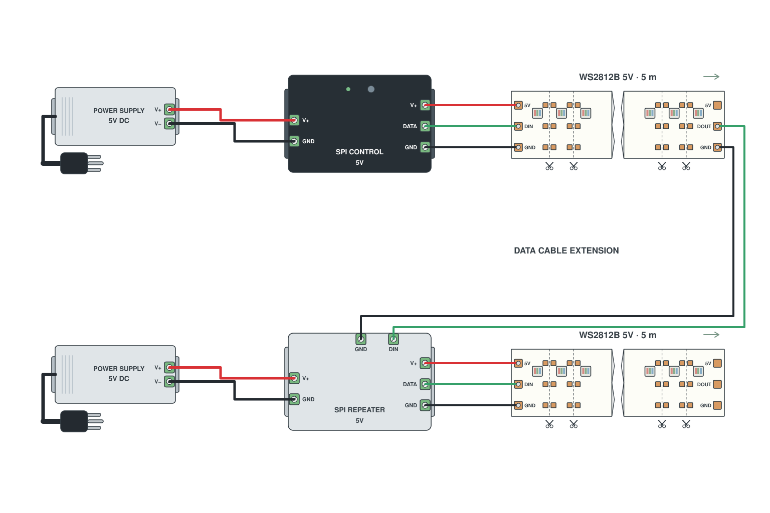
- Put an SPI signal amplifier where the previous section ends: signal IN from the strip, OUT to the next.
- Power the amplifier from the local supply.
- One amplifier every 5-10 m keeps the signal clean along 50 m.
Read more: How to wire addressable LED strips
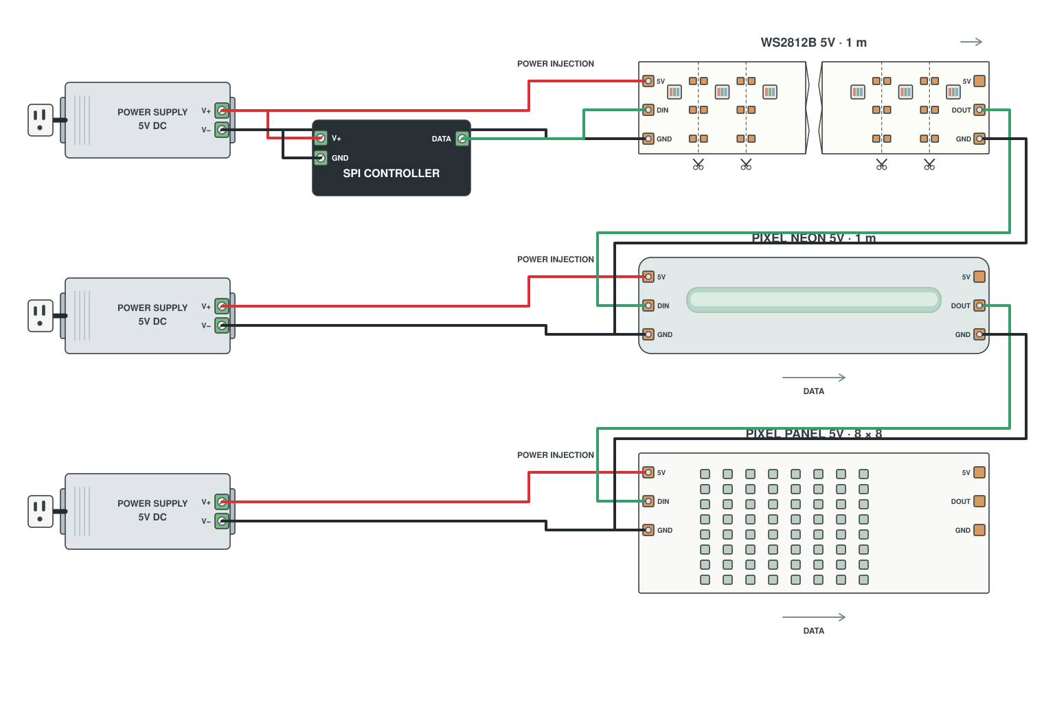
- Chain them for data in the order you want the effect to travel.
- Each item gets local power sized for its wattage.
- Set the controller pixel count to the total; a 5 m 60 LED/m strip is 300 pixels, a panel may be 256.
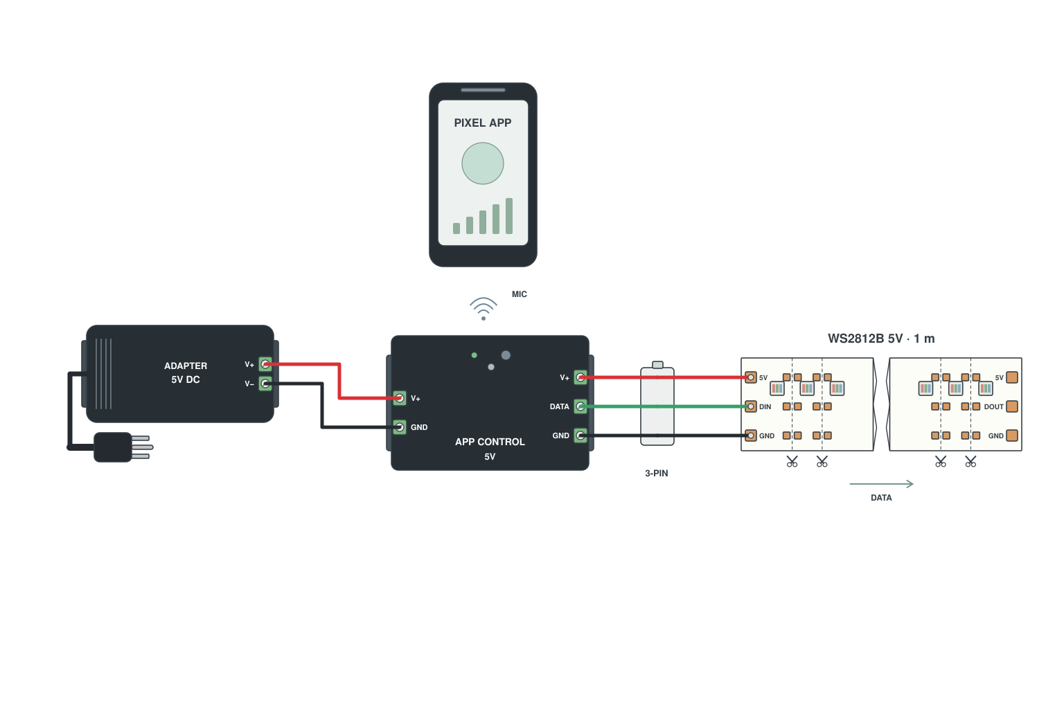
- SP-series controller: DC 5-24 V in, 3-pin JST out to the strip.
- Plug the JST into the strip IN end; power the controller from the strip supply.
- App pairs by Bluetooth or WiFi; set the IC type and LED count in the app.
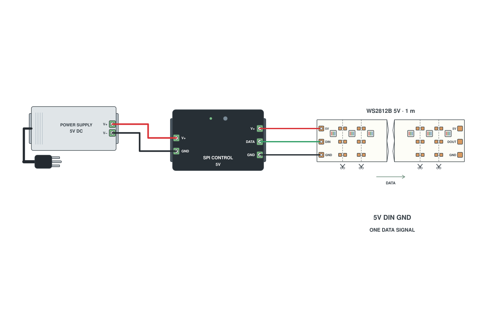
- Pads: 5 V (or 12/24 V), DIN (data in), GND. The arrow on the strip points away from the input.
- Controller DATA to DIN, controller GND to GND; strip V+ from the supply.
- Data goes one way: if you connect to the DOUT end nothing lights.
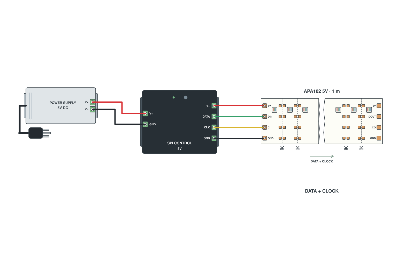
- Pads: V+, CLK (clock), DAT (data), GND.
- Controller must have both CLK and DAT outputs (SPI 4-wire); wire them to the matching pads.
- Common GND between controller, supply and strip as always.
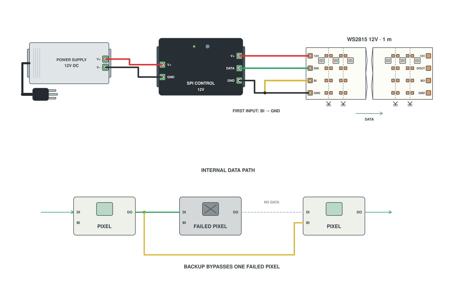
- Breakpoint-resume LED strips (WS2815, WS2813, SK6813) have four pads: V+, DI, BI (backup in), GND.
- Each pixel receives data on DI and also a copy from the pixel before last on BI.
- If one pixel fails, the next pixel reads the copy on BI and the chain keeps running.
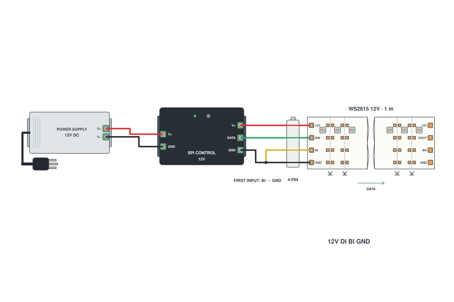
- Use a 4-pin clip or a 4-wire lead: V+, DI, BI, GND.
- Controller DATA goes to DI; the BI pad of the first pixel is tied to GND, which is what the WS2815 datasheet application circuit shows.
- V+ from the supply, GND common with the controller.
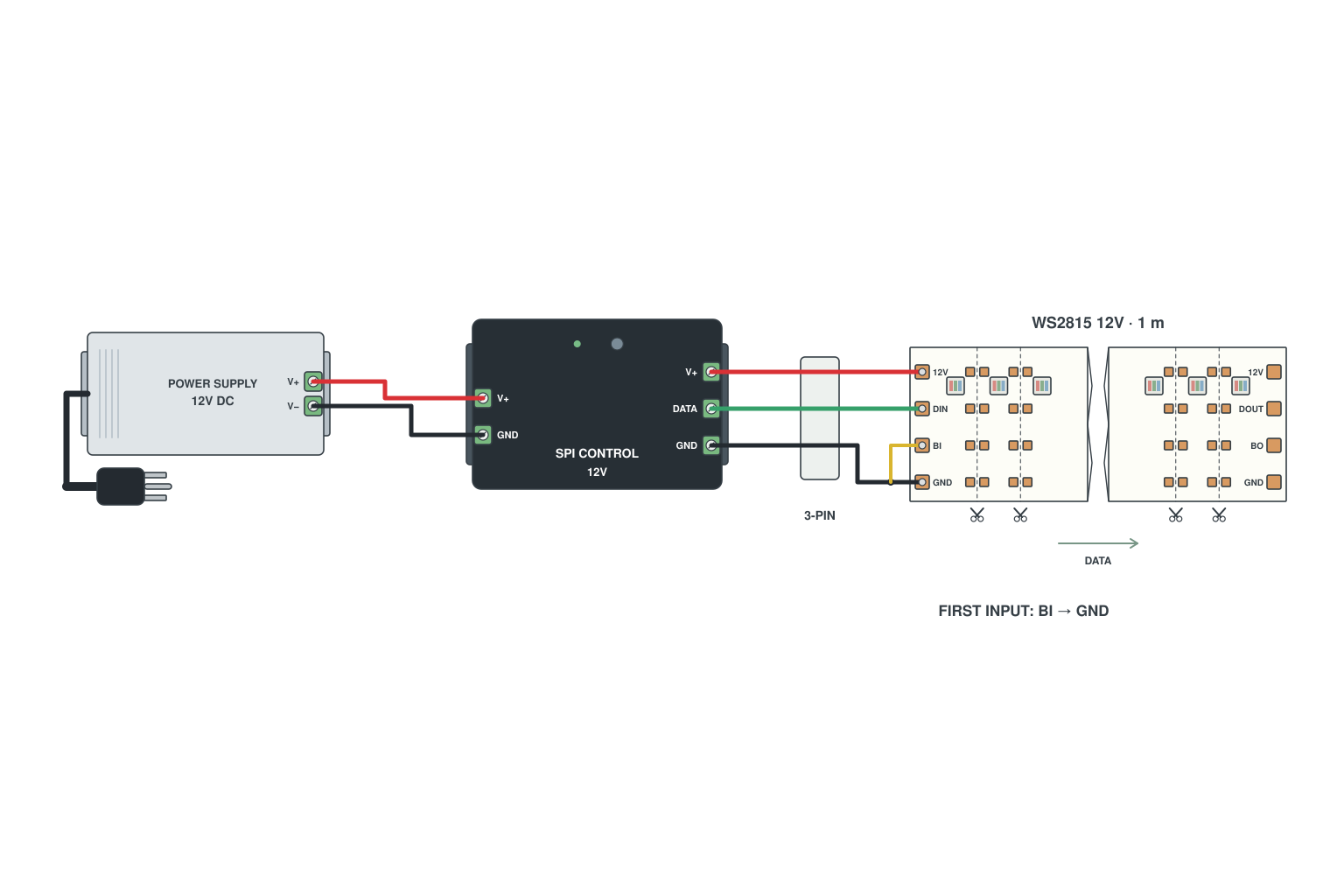
- Cut the strip at a cut mark so the four pads are exposed.
- Solder a short jumper from the BI pad to the GND pad at the input.
- Connect the JST: V+ to V+, DATA to DI, GND to GND.
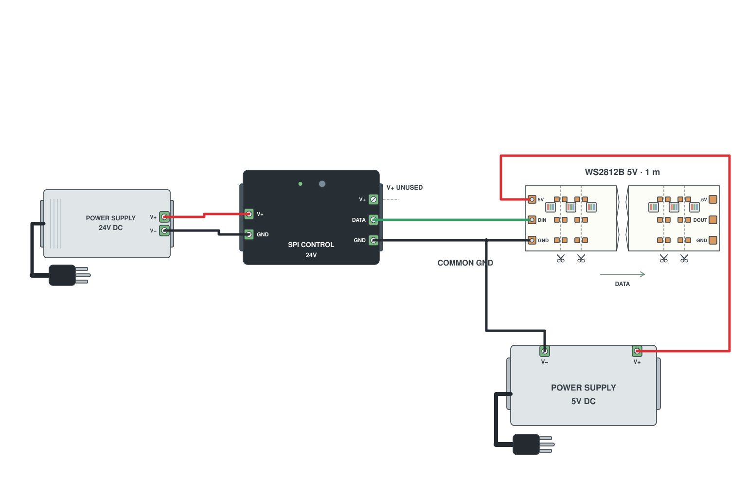
- Give the controller its own supply at its rated voltage.
- Give the strip its own supply at the strip voltage; strip V+ never comes from the controller.
- Join the GND of both supplies, the controller and the strip; DATA from controller to strip.
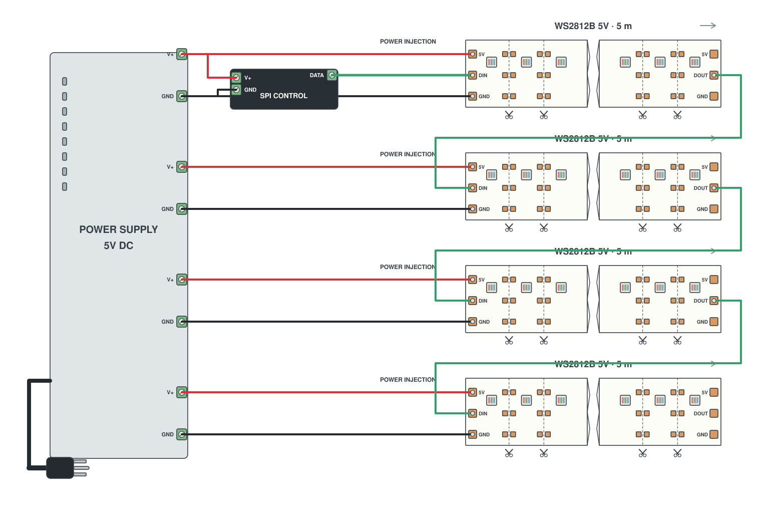
- Size the supply for the whole run: 20 m of 5 V WS2812B at 18 W/m is 360 W, 72 A.
- Run a pair of heavy wires (10-12 AWG) along the strip; tap V+ and GND into the start of every 5 m section.
- Data still chains from section to section; only power is injected.
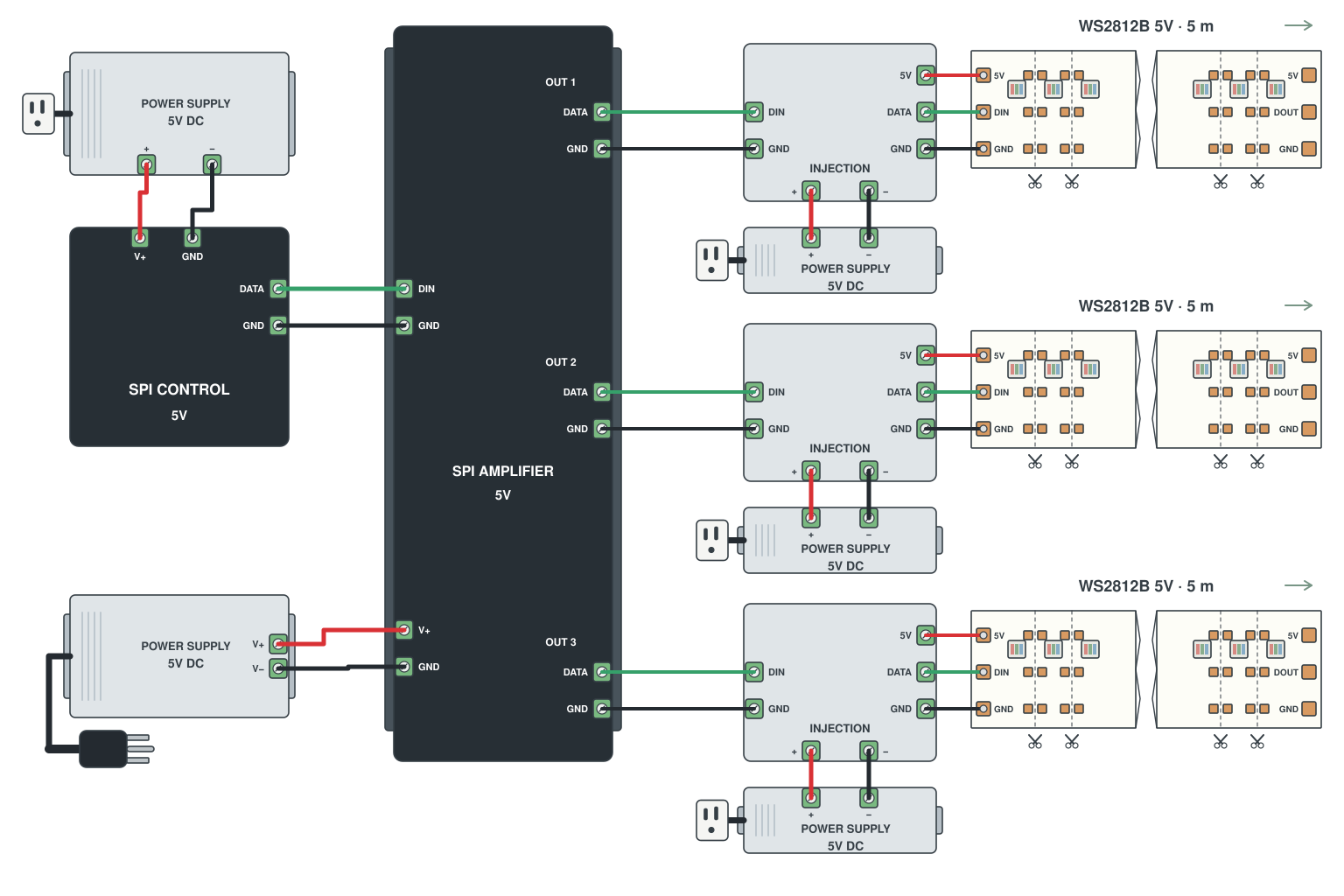
- Controller DATA into the input of a multi-channel SPI amplifier.
- Each amplifier output drives its own strip section; each section has its own supply.
- All sections show the same effect in sync; long data cables between them are fine.
Read more: How to wire addressable LED strips
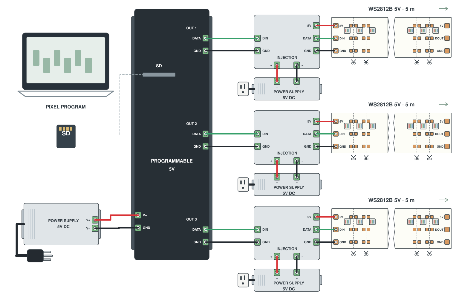
- Create the effect in LedEdit on a PC and copy it to the SD card.
- T-300K: 8 outputs, each feeding a strip section with its own supply; K-1000C: single output for smaller jobs.
- Controller power separate from strip power; GND common.
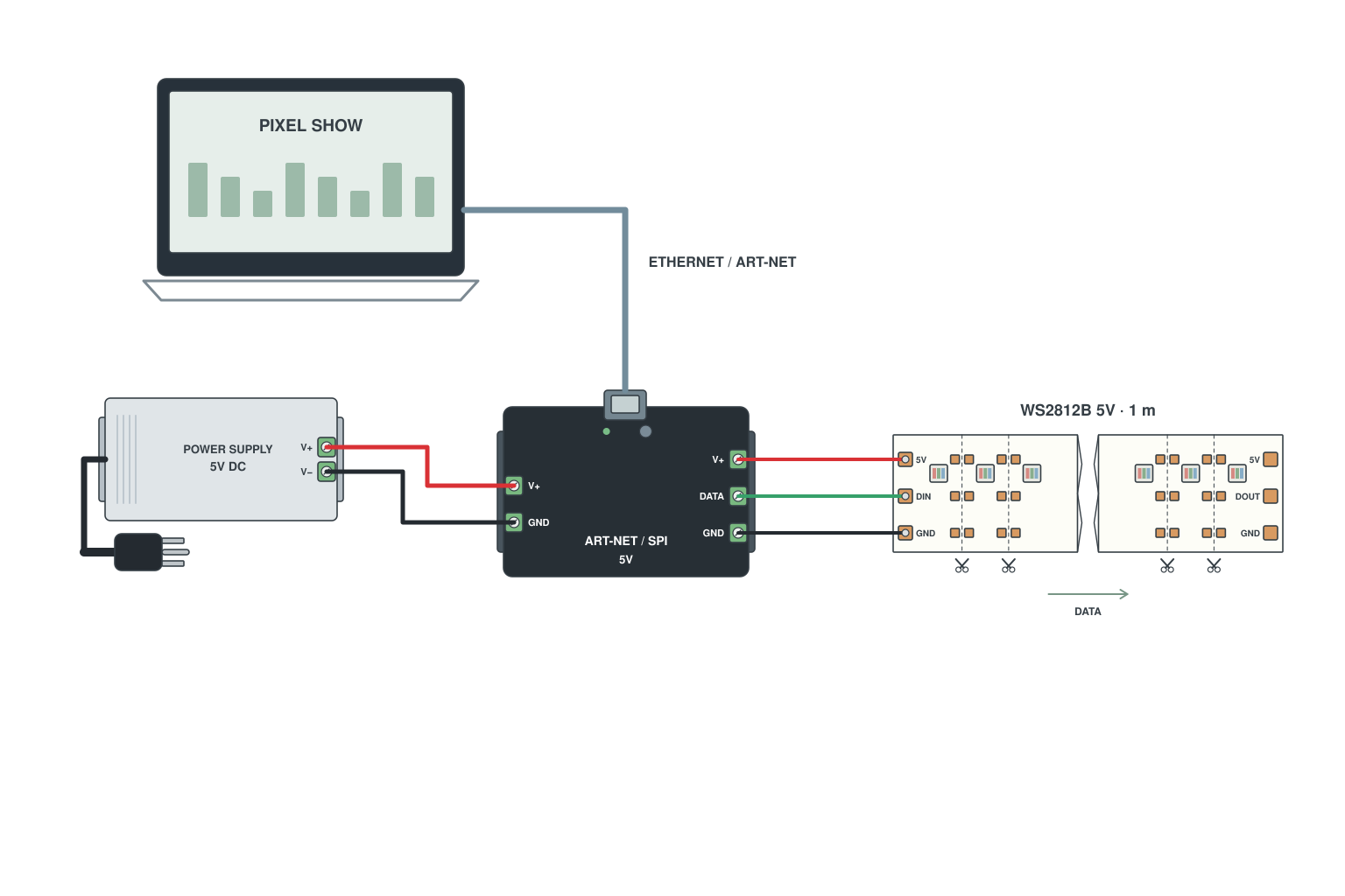
- Console or PC into an Art-Net / DMX-to-SPI decoder (network cable or XLR).
- Decoder DATA output to the addressable LED strip; 24 V supply into the decoder.
- Map DMX channels to pixel groups in the decoder settings.

- On a single-signal strip every pixel repeats the data to the next; a dead pixel stops the chain, all pixels after it go dark.
- On a breakpoint-resume LED strip the next pixel reads the backup line and carries on.
- For anything you cannot easily reach after installation, pay the little extra for WS2815 or SK6813.
Read more: WS2815 vs WS2812B
110 V and 220 V high-voltage LED strip wiring
No power supply, 50 m from one plug, and how to dim them. This is mains voltage, so read the safety notes and get an electrician for the plug end if your local rules require it.
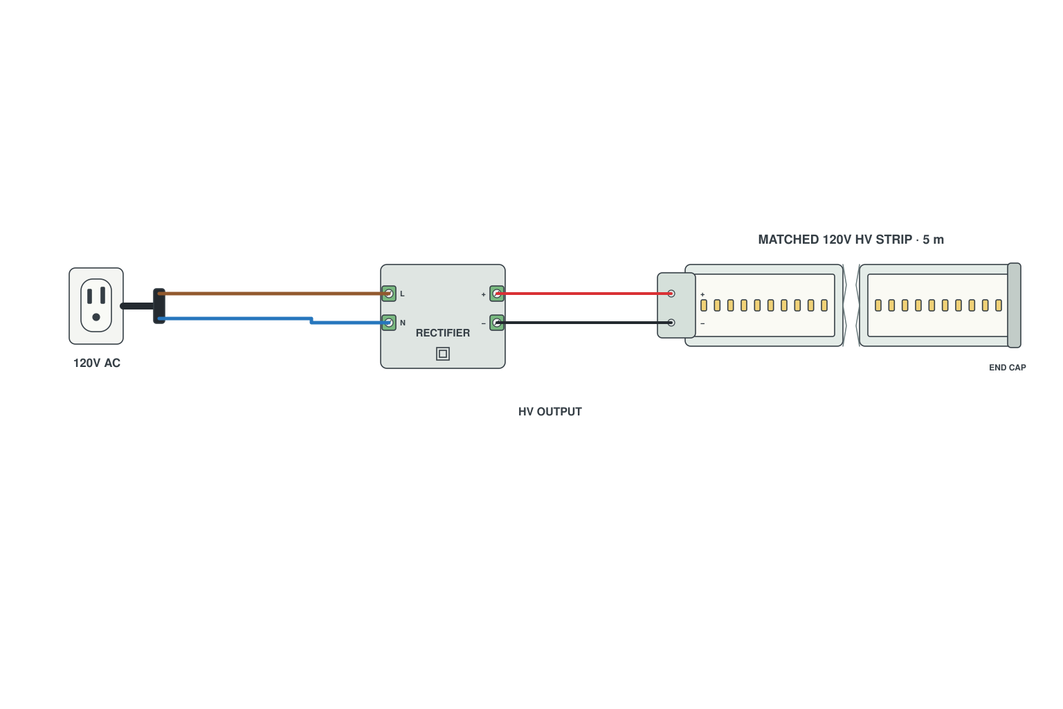
- Cut only at the 50 cm or 100 cm mark printed on the strip.
- Push the 2-pin plug into the cut end, fit the inline rectifier and mains plug; press the end cap on the far end and seal it.
- Plug in; no separate power supply is needed.
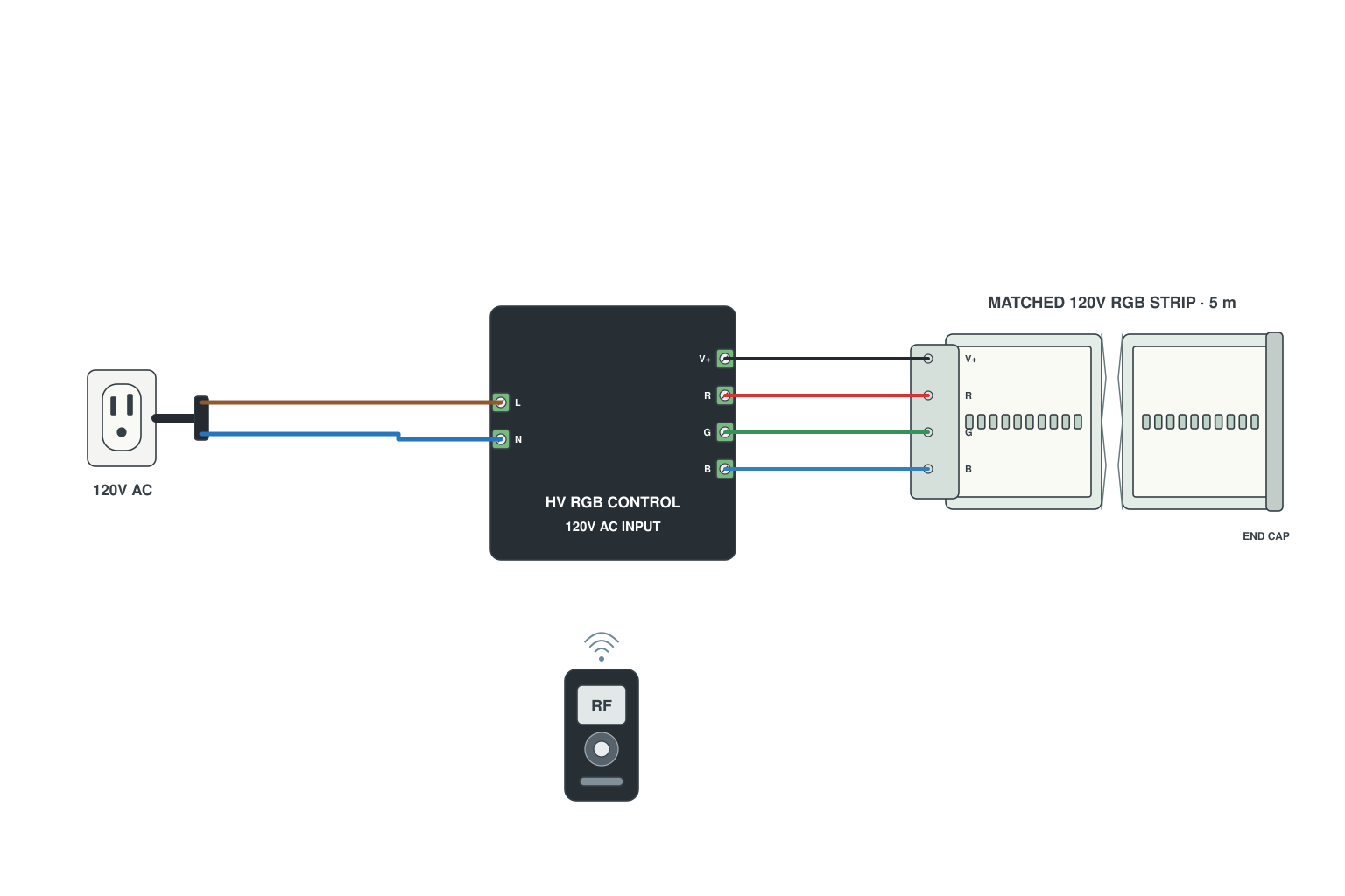
- Mains plug into the high-voltage RGB controller; 4-pin plug from the controller into the strip.
- The controller contains the rectifier, so no other box is needed.
- Pair the remote; the whole run changes colour together (no amplifier needed up to the controller rating, usually 50 m).
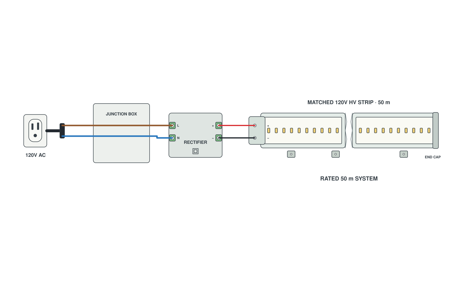
- One plug, one strip, up to 50 m (some types 100 m) with no visible drop because the current is so low at 220 V.
- Support the strip every 50 cm with clips; do not let the plug end hang on its own weight.
- Run the mains cable to the start through a weatherproof junction box.
Read more: High voltage vs low voltage strips
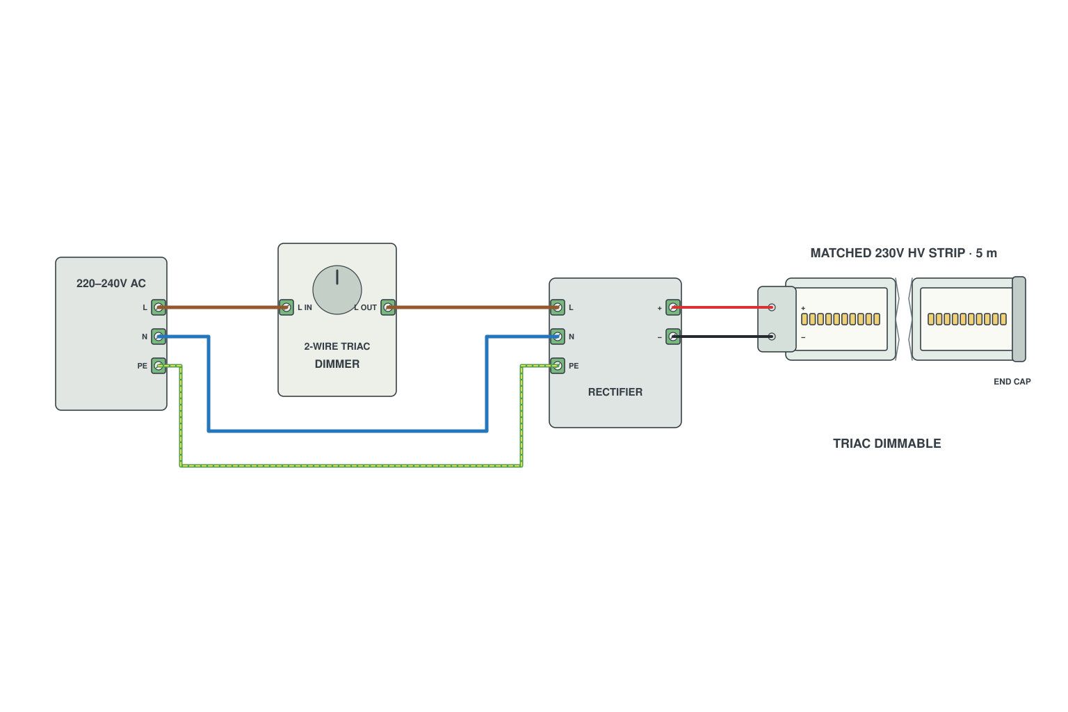
- The strip must be marked TRIAC dimmable or use the RF high-voltage dimmer box.
- Wall TRIAC dimmer in series with the live wire, then the rectifier, then the strip.
- Set the dimmer minimum so the strip does not flicker at the bottom of the range.
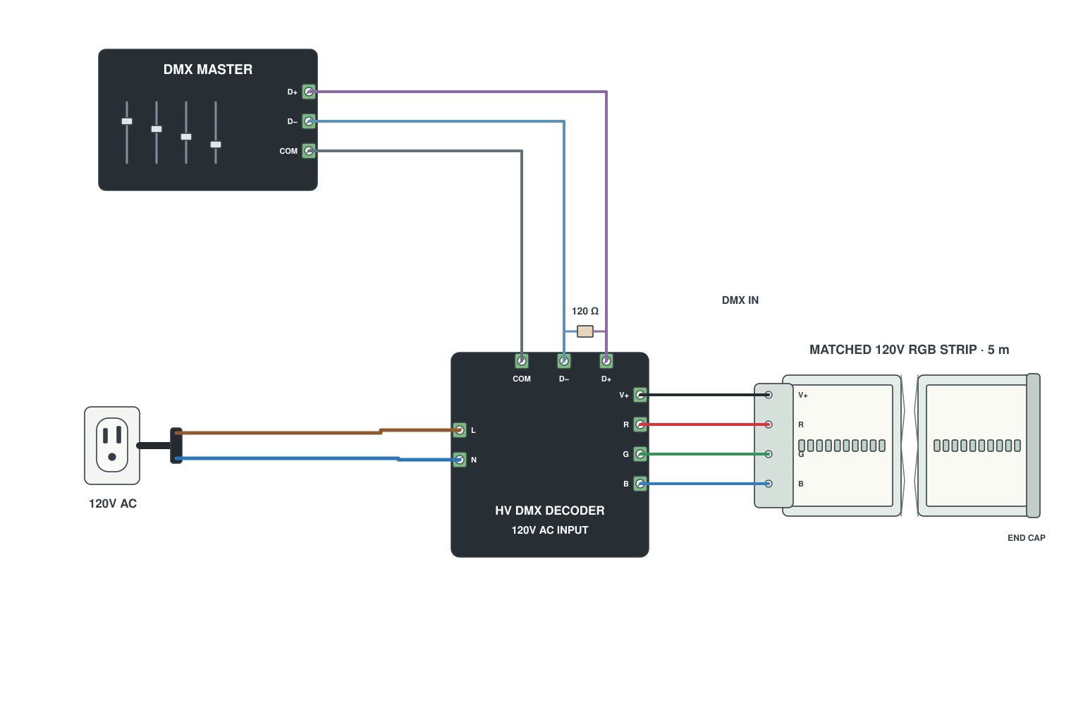
- Mains into the high-voltage DMX decoder; console into DMX IN.
- Decoder outputs to the 220 V RGB LED strip through its 4-pin plug.
- Chain decoders on the DMX line, terminate the last one.
LED strip wiring for 0-10 V, DALI, DMX, TRIAC and smart control
Wiring for building-control and stage systems, plus the app-and-wall-switch combination most home projects end up with. If your electrician or lighting designer specified one of these, this is the section to send them.
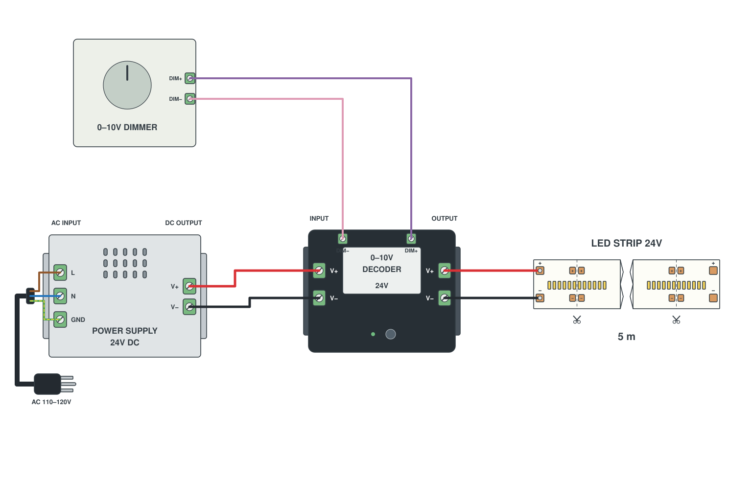
- 0-10 V wall dimmer: two thin wires (DIM+ and DIM-) to the dimming input of a 0-10 V decoder or driver.
- Decoder power: 24 V from the supply; decoder output to the strip.
- Several decoders can share one dimmer signal; keep polarity of the DIM wires consistent.
Read more: 0-10 V dimming explained
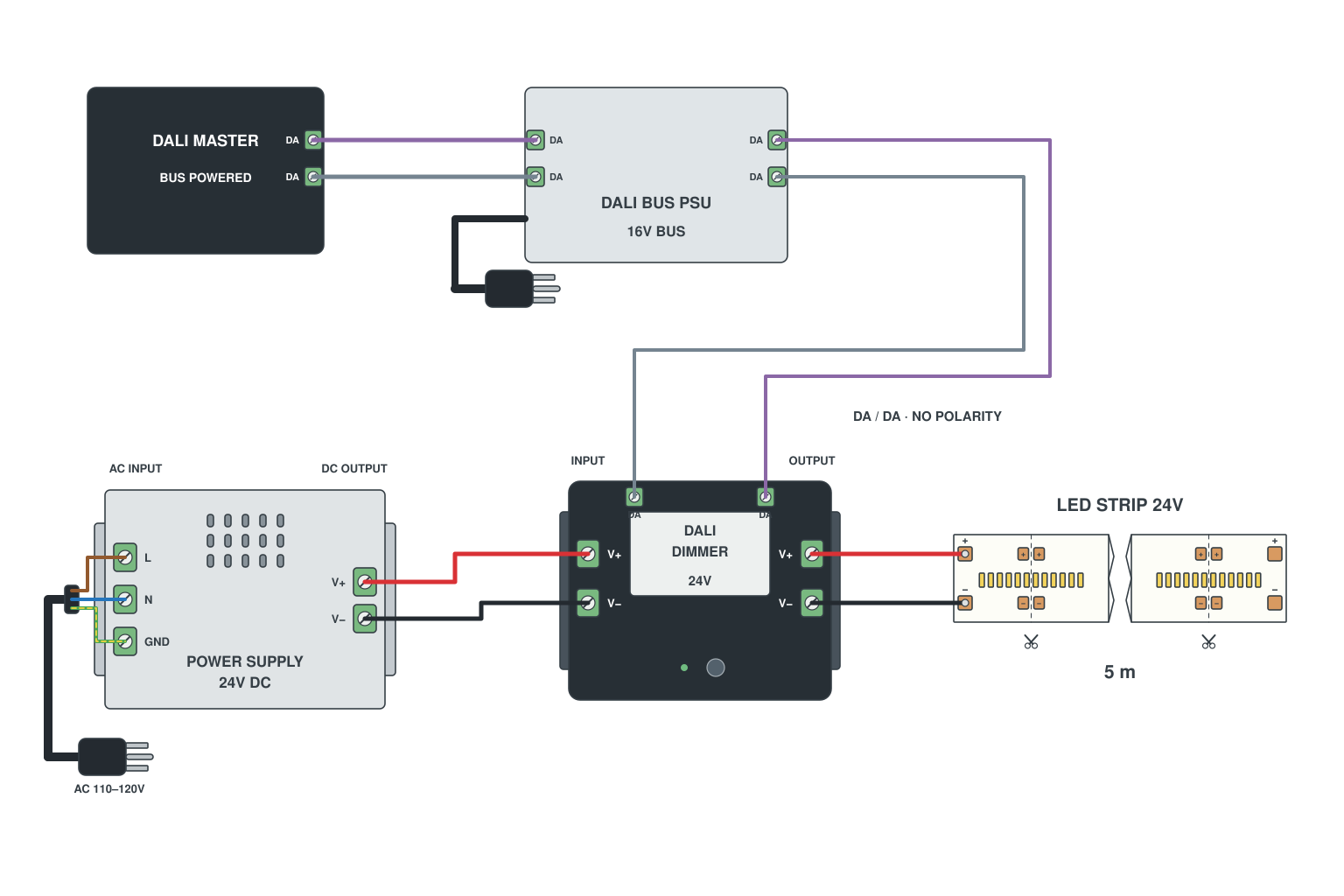
- DALI bus needs its own bus power supply (DALI PSU) and two wires DA+/DA-, polarity-free.
- Each strip gets a DALI dimmer (or a DALI dimmable driver) on the bus; the dimmer also takes 24 V from a normal supply and feeds the strip.
- Address each dimmer from the DALI master; up to 64 addresses per line.
Read more: What is DALI dimming?
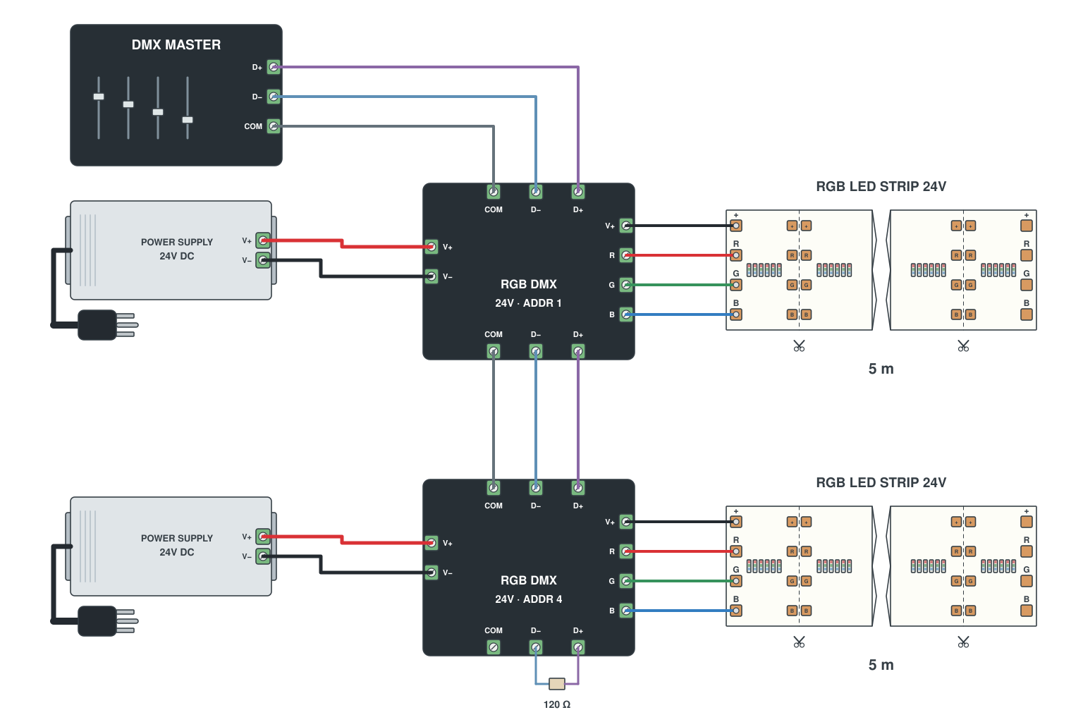
- Console XLR out to the decoder DMX IN; decoder DC 24 V from the supply; decoder RGB out to the strip.
- Chain DMX OUT of one decoder to DMX IN of the next; set each decoder start address (1, 4, 7 for RGB).
- Fit a 120 ohm terminator in the last DMX OUT.
Read more: DMX control of LED strips
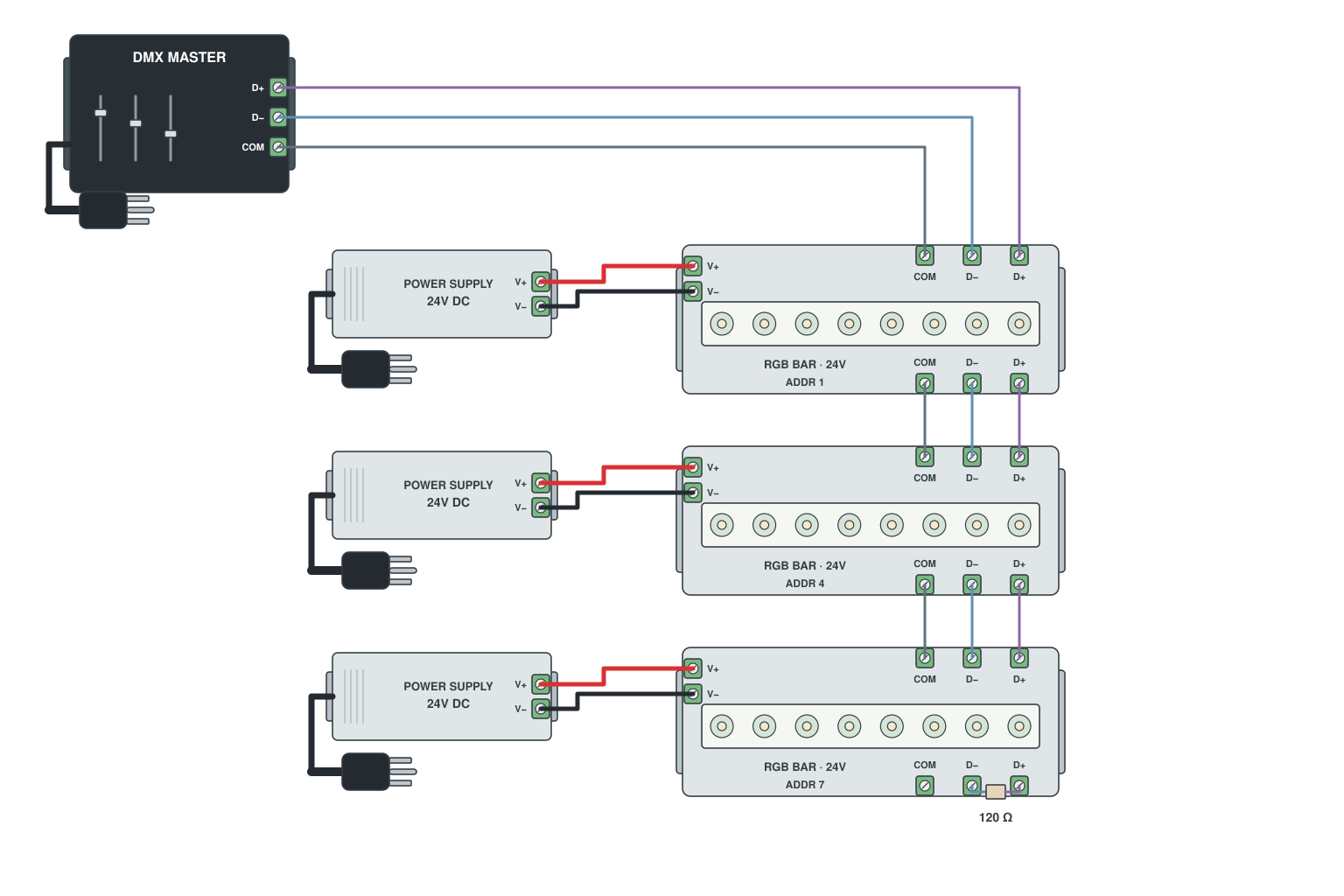
- Each fixture has DMX IN and OUT (3-pin or 5-pin): daisy-chain in line; power cable separate from the DMX cable.
- Set addresses so each fixture occupies its own channels (RGB = 3, RGBW = 4).
- Console or DMX master at the start of the chain; terminator at the end.
Read more: DMX control of LED strips
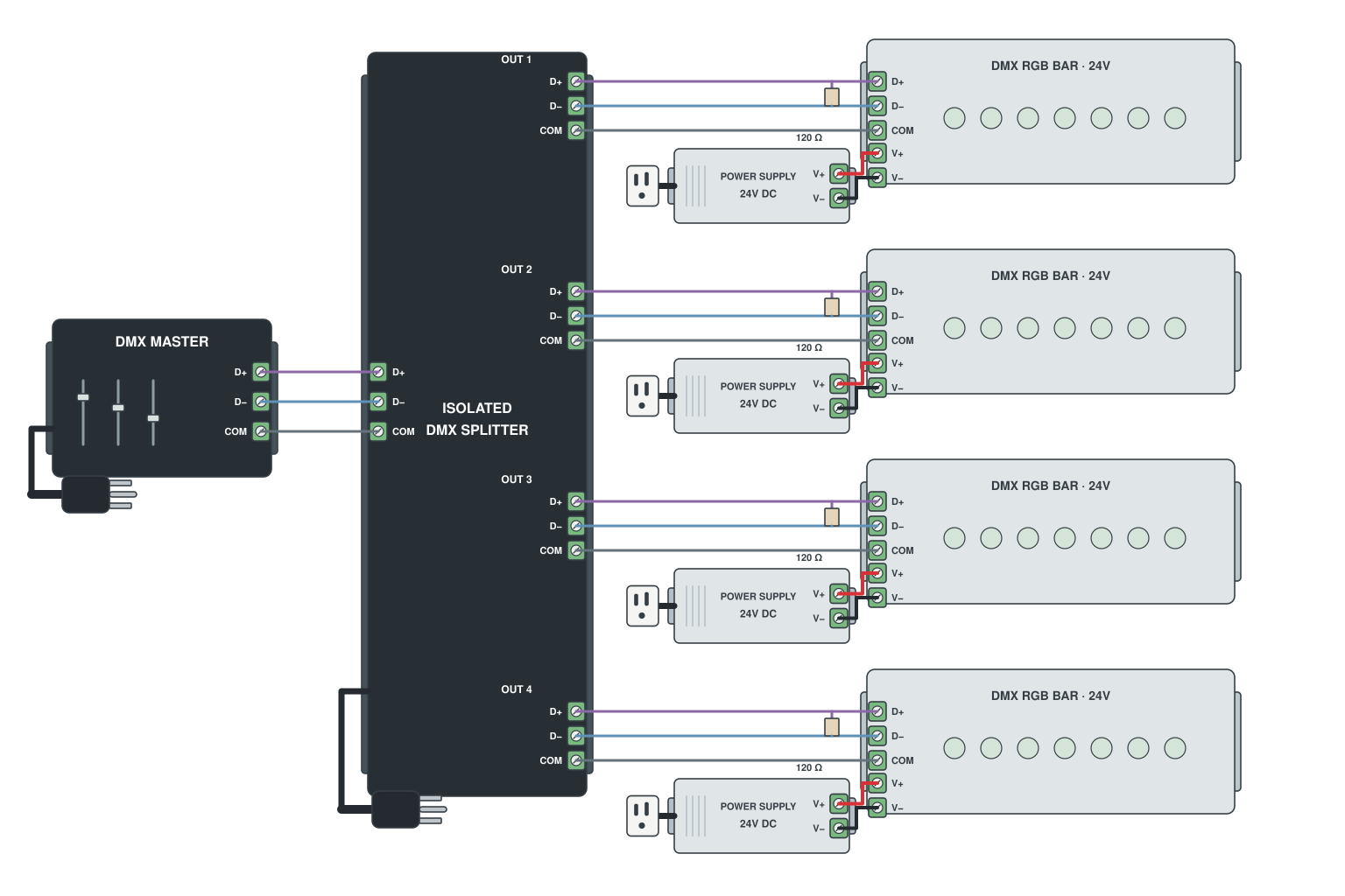
- Console into the DMX splitter (1 in, 4 or 8 out).
- Each output feeds a separate branch of decoders or fixtures, up to 32 devices per branch.
- Terminate the end of every branch.
Read more: DMX control of LED strips
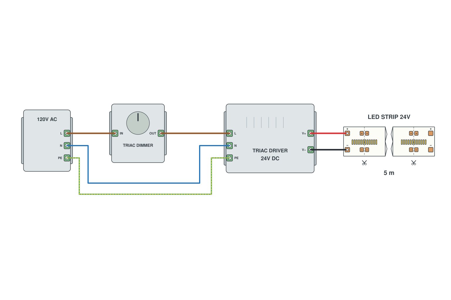
- Wall TRIAC dimmer in the mains line feeding a TRIAC-dimmable 24 V driver.
- Driver output to the strip; no extra controller.
- Match driver wattage to the strip; check the dimmer minimum load.
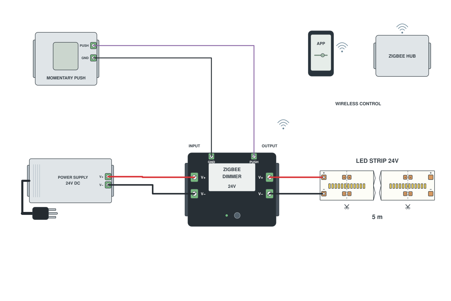
- WiFi or Zigbee controller between supply and strip (single colour, CCT, RGB or RGB+CCT versions).
- Optional momentary push switch on the PUSH input: short press on/off, hold to dim.
- Pair in the Tuya / Smart Life app; add to Alexa or Google Home from there.
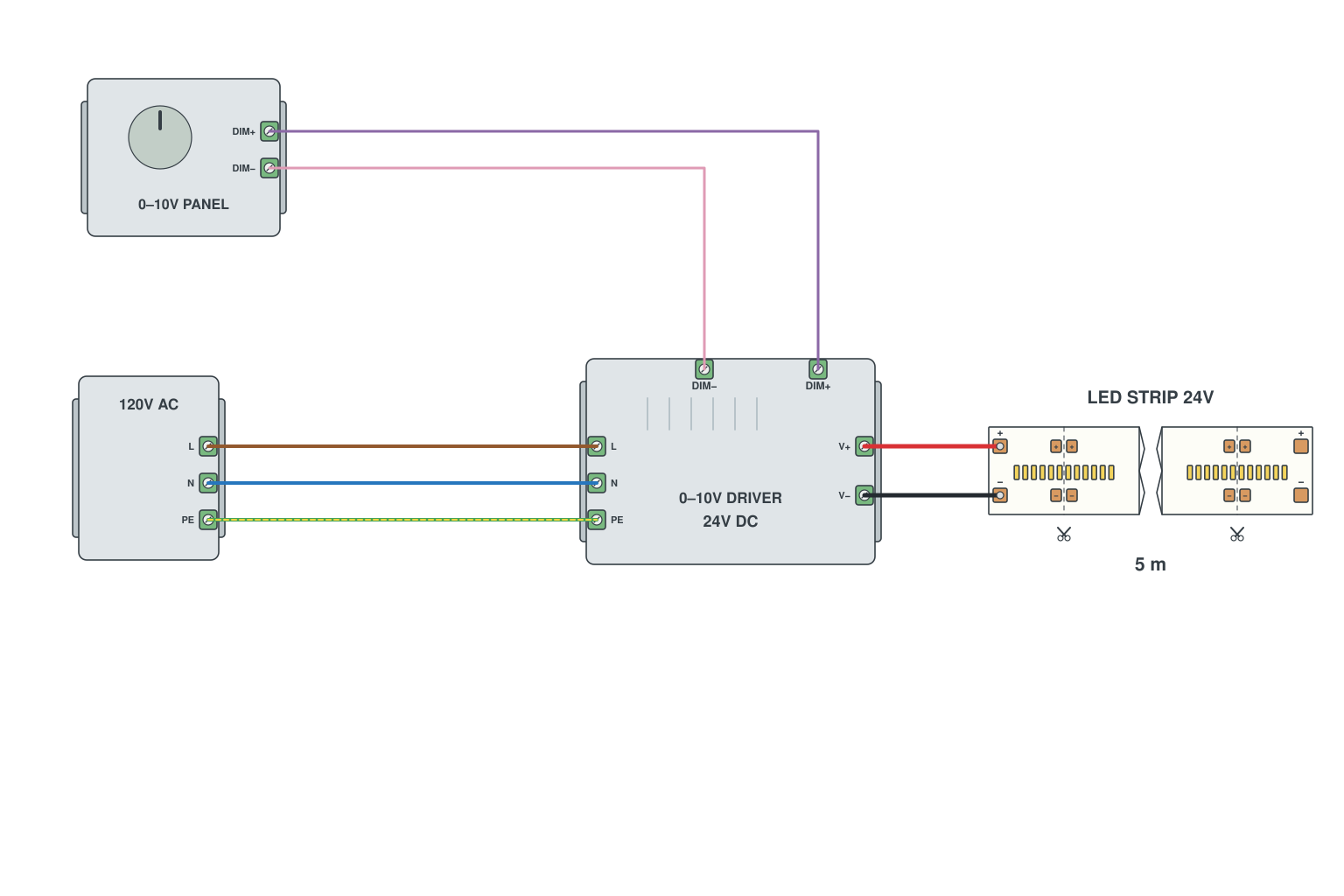
- Panel dimmer output DIM+ / DIM- to the driver dimming input.
- Mains into the driver, 24 V out to the strip.
- Several drivers can share one panel signal.
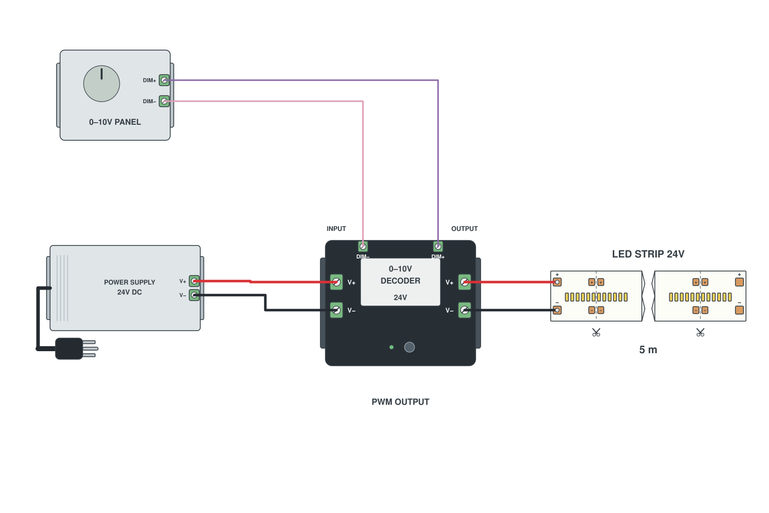
- Supply 24 V into the 0-10 V dimming decoder.
- Wall dimmer DIM+ / DIM- into the decoder; decoder output to the strip.
- The decoder does the PWM; the wall dimmer only sends the level.
Read more: 0-10 V dimming explained
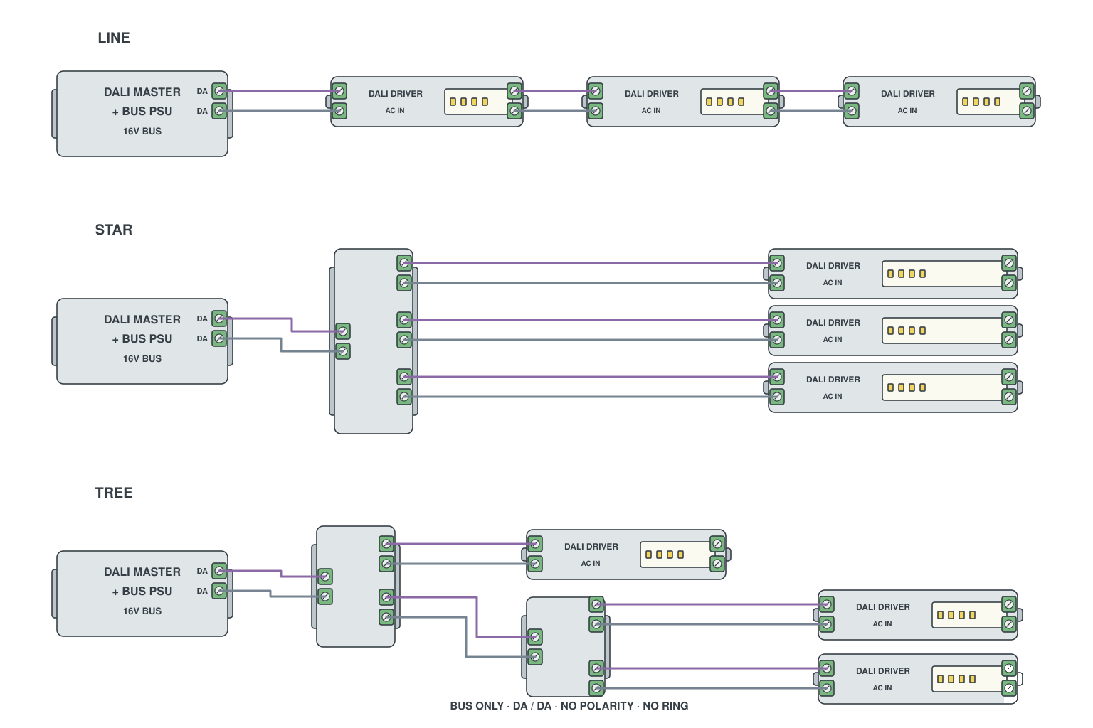
- DALI is a two-wire bus, polarity-free, that can be run as a line, a star, a tree or a daisy chain.
- One DALI bus power supply per line, up to 64 addresses.
- Every strip has a DALI dimmer or driver on the bus plus its own mains or 24 V supply.
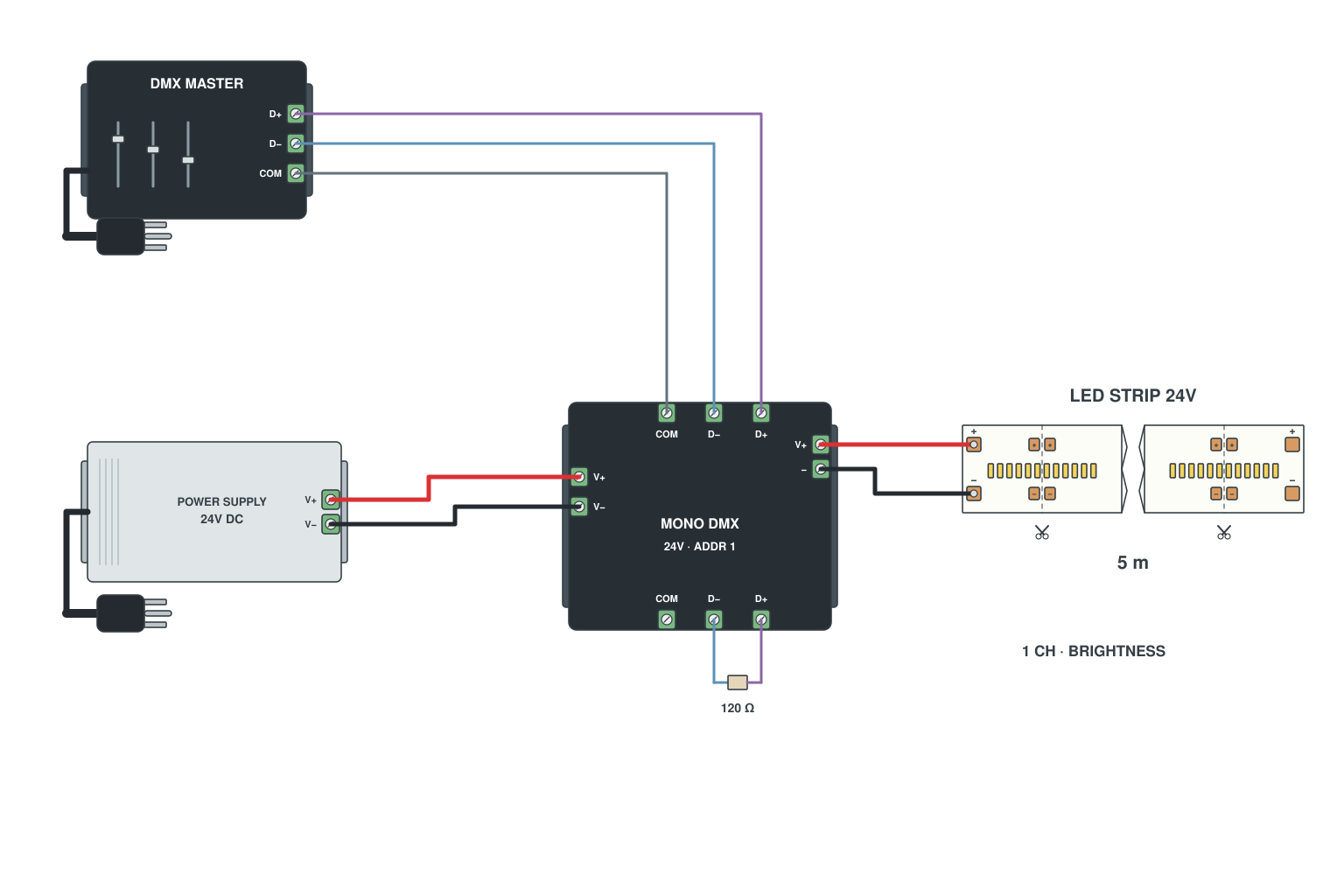
- DMX master or console into a 1-channel constant-voltage DMX decoder.
- 24 V supply into the decoder, decoder output to the strip.
- Set the start address on the decoder display; one channel = brightness.
Read more: DMX control of LED strips
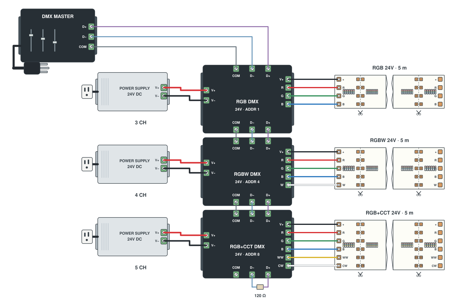
- Choose the decoder by channel count: 3 for RGB, 4 for RGBW, 5 (or 6) for RGB+CCT.
- Decoder outputs to the strip pads in order; 24 V supply into the decoder.
- Chain DMX IN/OUT between decoders; addresses 1, 4, 8, 13... so channels do not overlap.
Read more: DMX control of LED strips
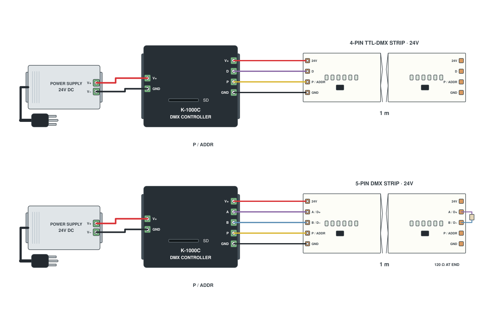
- DMX strip pads: V+, DATA+, DATA-, GND (4-pin) or with a separate clock (5-pin).
- DMX controller such as the K-1000C drives the strip directly; strip power from its own supply.
- Address the pixels once with the controller; no decoders needed.
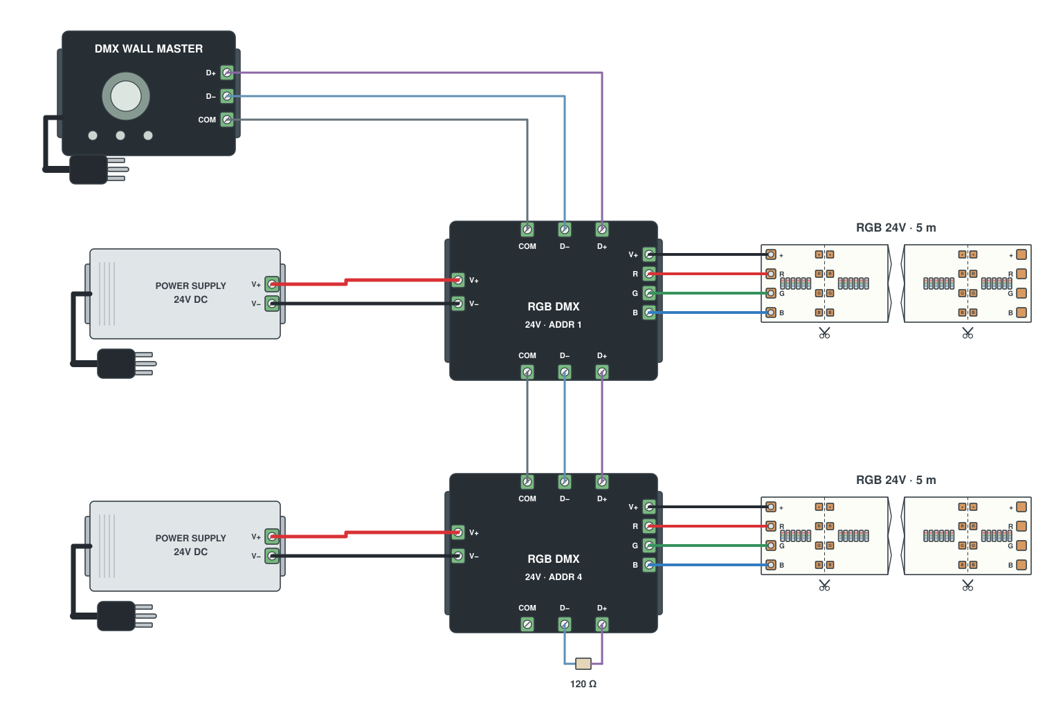
- Wall-mounted DMX master panel outputs DMX512 on its own.
- Chain the decoders from the panel; each decoder feeds a strip with a supply.
- Scenes and colours are picked on the panel.
Read more: DMX control of LED strips
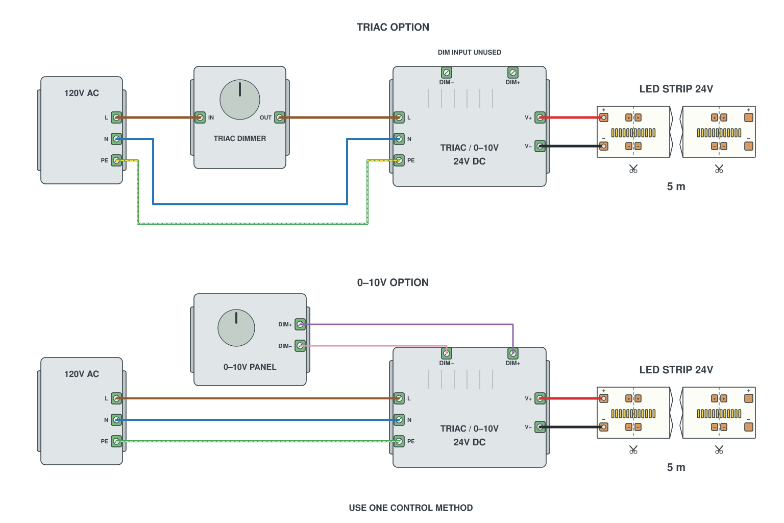
- TRIAC dimmer in the mains live wire, or 0-10 V panel on the DIM input; both terminals are on the driver.
- Mains into the driver, 24 V out to the strip.
- Use one method per installation, not both at once.
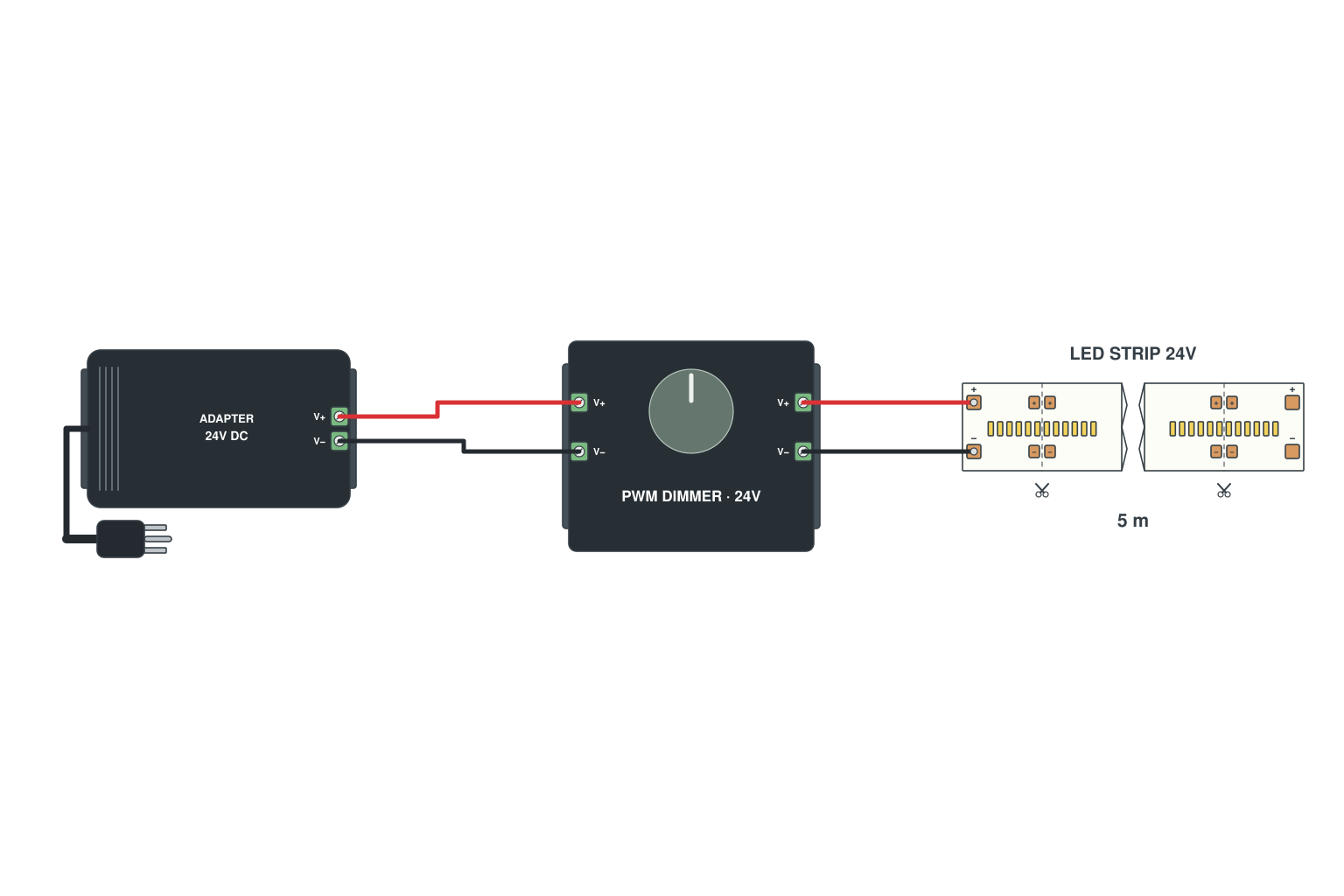
- 24 V supply into the PWM dimmer; dimmer output to the strip.
- Knob, touch or RF remote sets the level.
- PWM keeps the colour temperature constant while dimming.
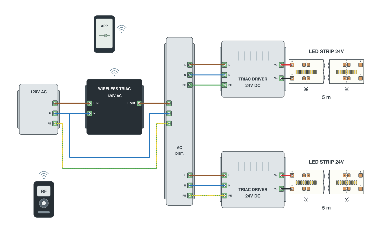
- Wireless TRIAC dimmer module in the mains line before the dimmable drivers.
- Each driver feeds its own strip.
- Phone app or RF remote sets the level; a wall dimmer can stay in the circuit too.
Read more: TRIAC dimming explained
LED strip connectors, soldering and waterproof joints
Strip-to-wire, strip-to-strip, wire-to-wire, and how to keep water out of every joint. Most of the strips that come back to us for warranty failed at a joint, not in the middle of the reel.
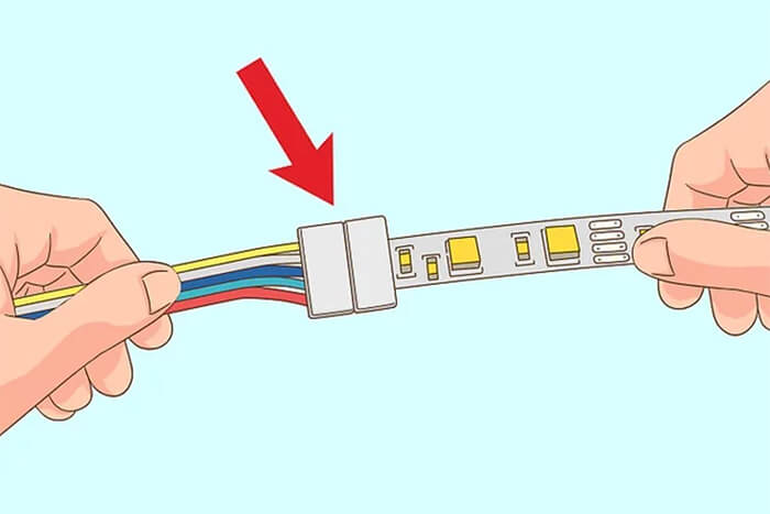
- Cut the strip cleanly at the cut mark; peel the last 5 mm of cover on waterproof types.
- Open the clip, slide the strip in until the pads sit under the metal teeth, close the clip firmly.
- Match wire colours: red to +, then the channel colours in pad order.
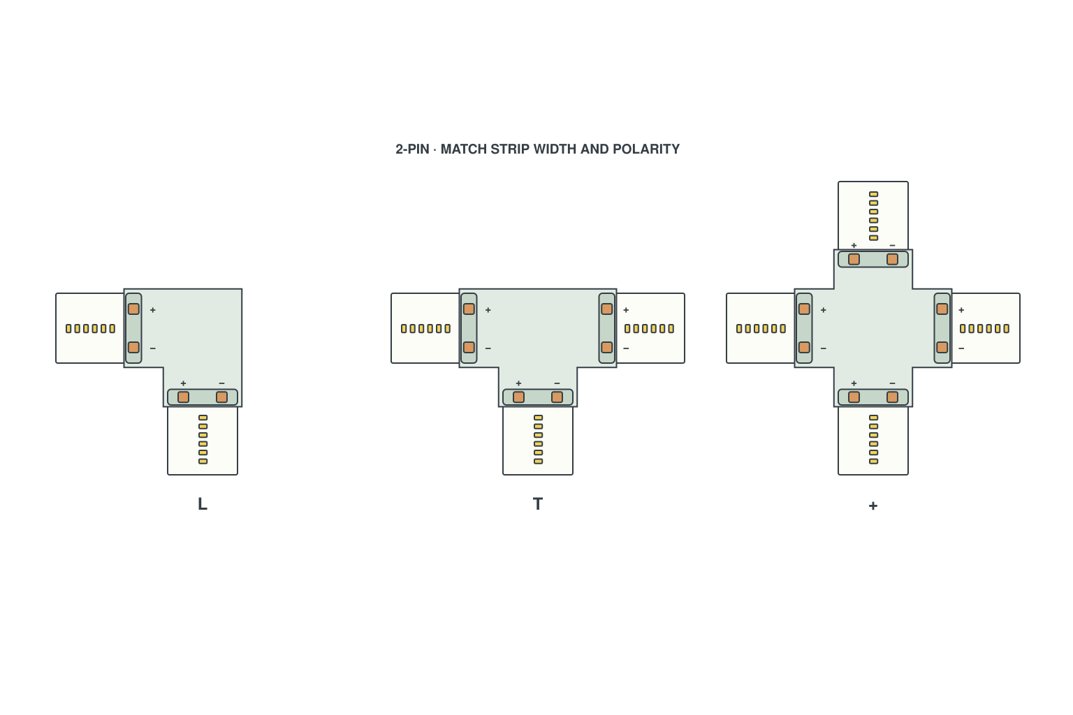
- L connector: two clips at 90 degrees for inside or outside corners.
- T connector: one input, two outputs, when a run branches.
- + connector: four ways; keep total current within the connector rating.
Read more: How to choose strip connectors
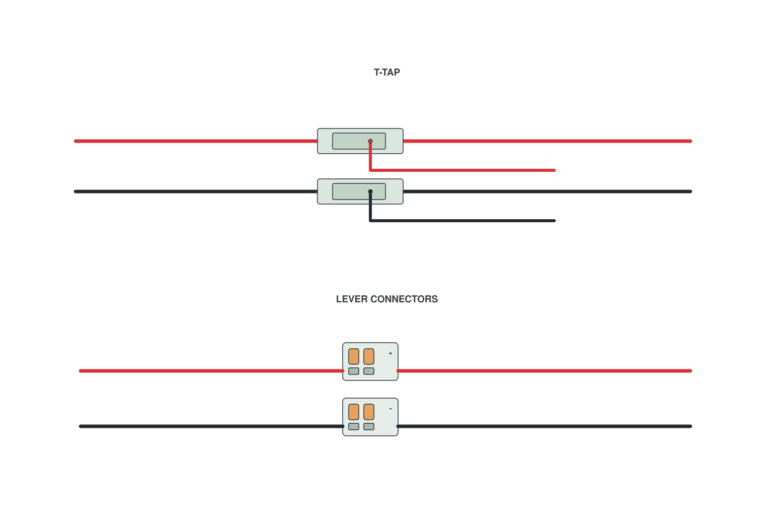
- T-tap: press the tap onto the main wire, insert the branch, close; no stripping.
- Lever connector: strip 10 mm, lift the lever, insert, close; two to five ways.
- Choose the size for the wire gauge printed on the connector.
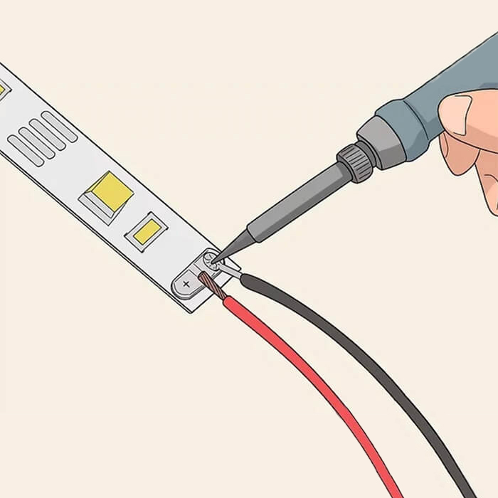
- Tin the pads and the wire ends with a little solder.
- Hold the wire on the pad and touch the iron for one second; do not overheat the strip.
- Cover the joint with heat-shrink or a drop of silicone.
Read more: How to connect LED strip lights · How to connect COB LED strips
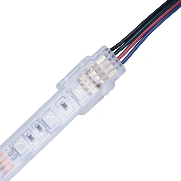
- Use IP67/IP68 male-female plug connectors with the O-ring seated; hand-tighten the nut.
- Cables entering a box go through a PG gland sized to the cable.
- Leave a drip loop so water runs away from the connector.
Read more: Cutting and connecting waterproof LED strips
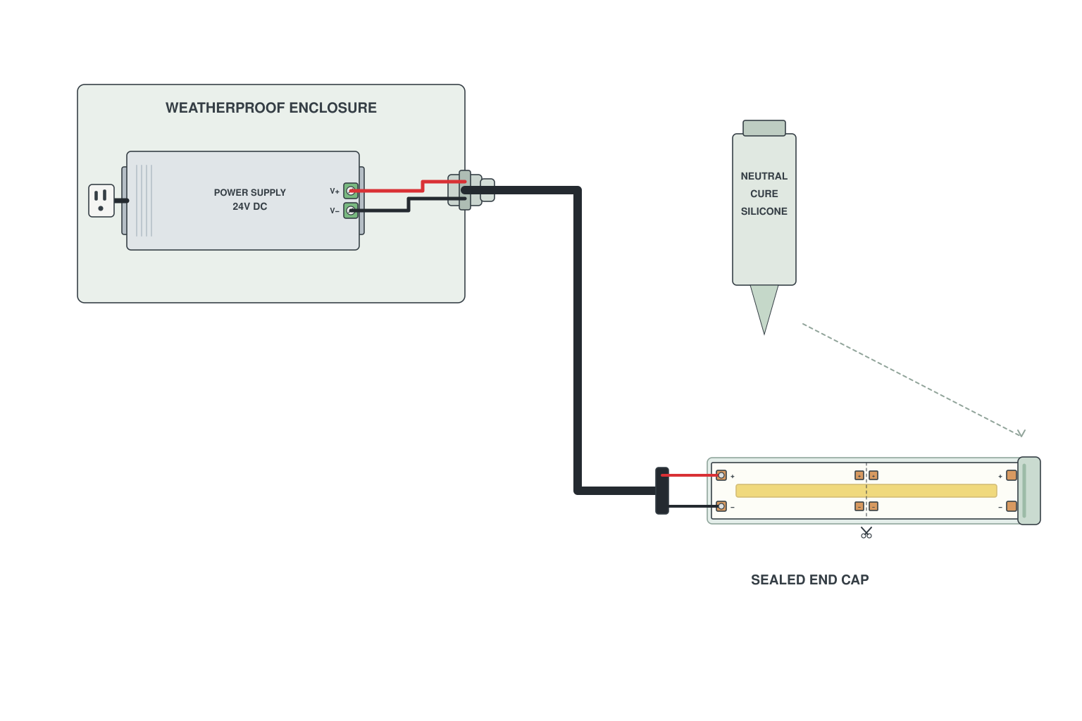
- Slide the end cap on, fill with neutral-cure silicone, let it cure before exposing to rain.
- Put connectors and the driver inside an IP65 junction box; cables through glands.
- Mount the box above the strip so cables slope away from it.
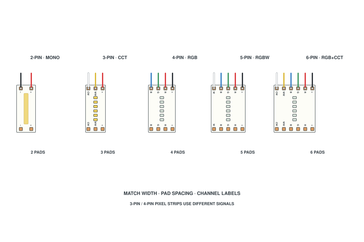
- Count the pads at the cut mark: 2 (single colour), 3 (CCT or addressable), 4 (RGB or dual-signal), 5 (RGBW), 6 (RGB+CCT).
- Check the strip width: 8 mm, 10 mm or 12 mm connectors are not interchangeable.
- Pick strip-to-wire, strip-to-strip or corner type as needed.
Read more: How to choose strip connectors
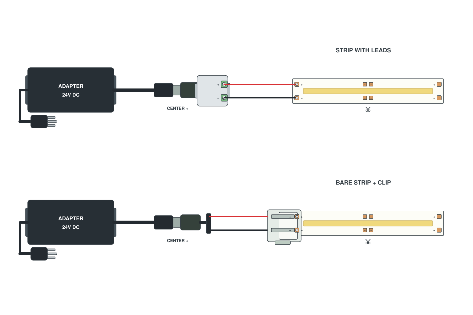
- Strip with wires: push the wires into a DC female jack terminal, plug it into the adapter.
- Strip cut bare: use a clip-to-DC-jack connector, then the adapter.
- Check +/- on the jack; centre pin is + on our adapters.
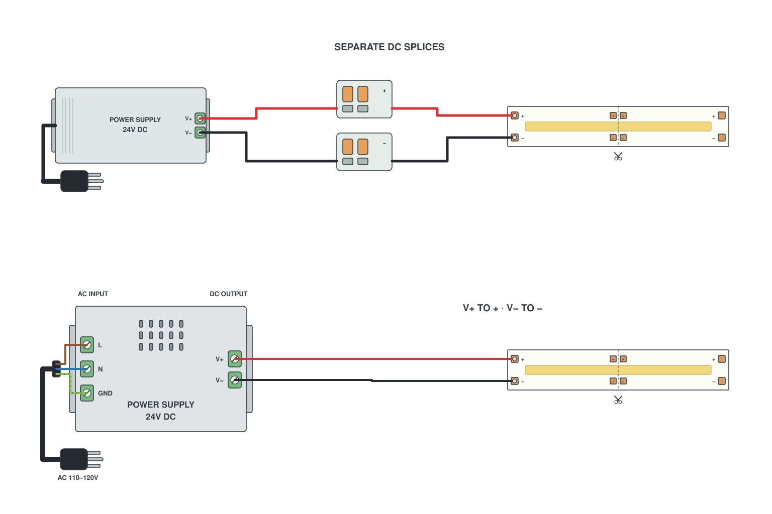
- Bare wires both sides: twist together and cap with a wire nut, or use a lever connector.
- Screw terminals: strip 8 mm of insulation, insert, tighten, tug to check.
- V+ to V+, V- to V-; on the mains side L, N and earth exactly as marked.
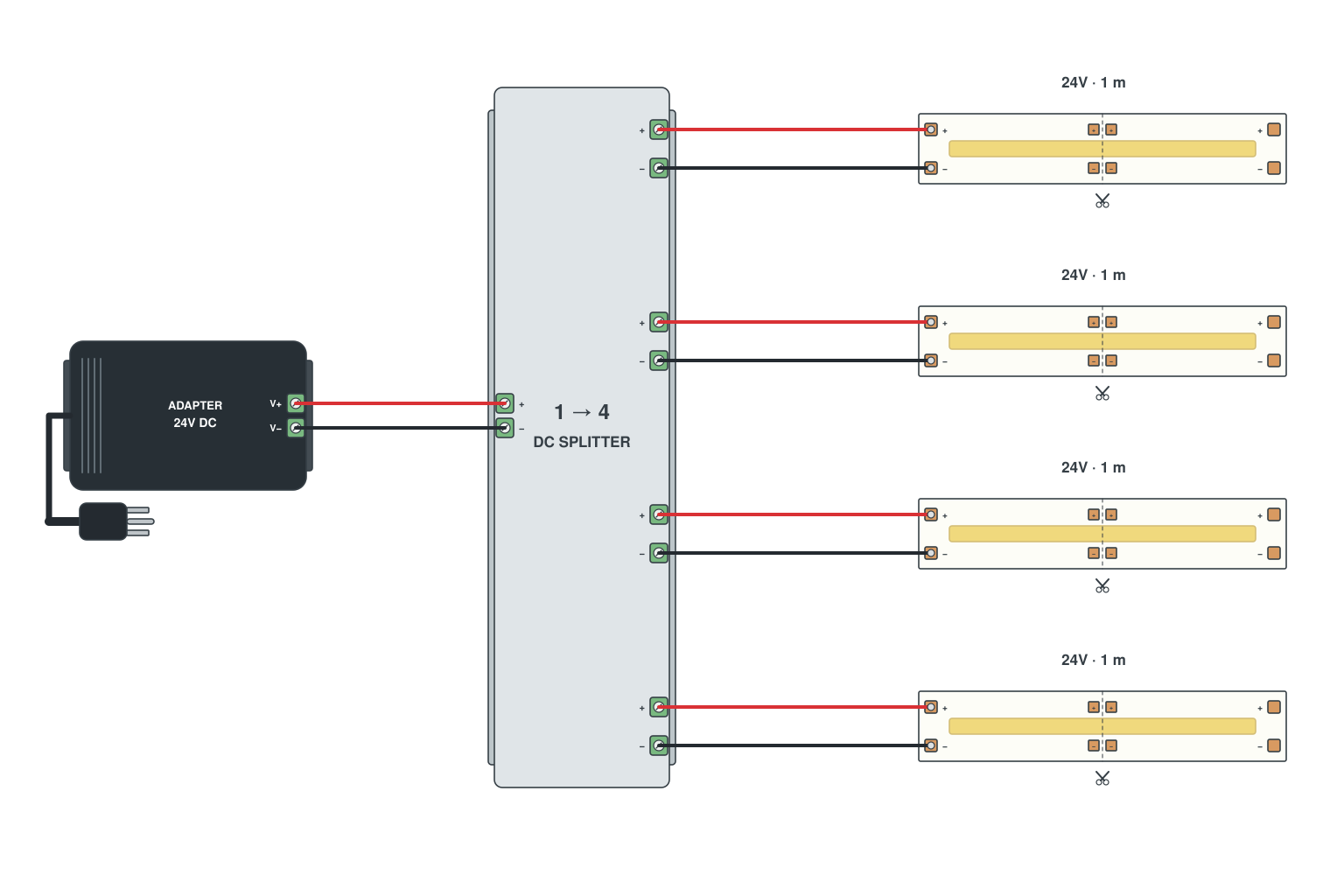
- 1-to-2, 1-to-4 or 1-to-8 DC splitter into the adapter.
- Each strip on its own branch; total watts within the adapter rating.
- All strips switch and dim together.
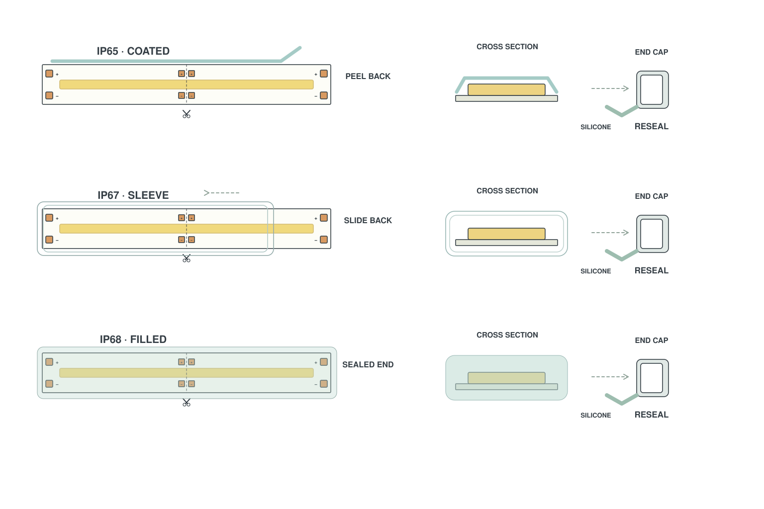
- IP65 (silicone coat): cut at the mark with scissors, peel the coating off the last pad.
- IP67 (silicone sleeve): cut, slide the sleeve back to expose the pads.
- IP68 (filled tube): cut, then re-seal the new end with the end cap and silicone.
Read more: Cutting and connecting waterproof LED strips
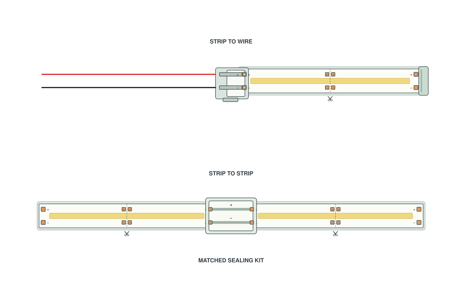
- Strip-to-wire: push the exposed pads into the IP67 clip, close it, run the wire.
- Strip-to-strip: both strip ends into the double clip.
- Seal the clip with the supplied silicone cap or heat-shrink.
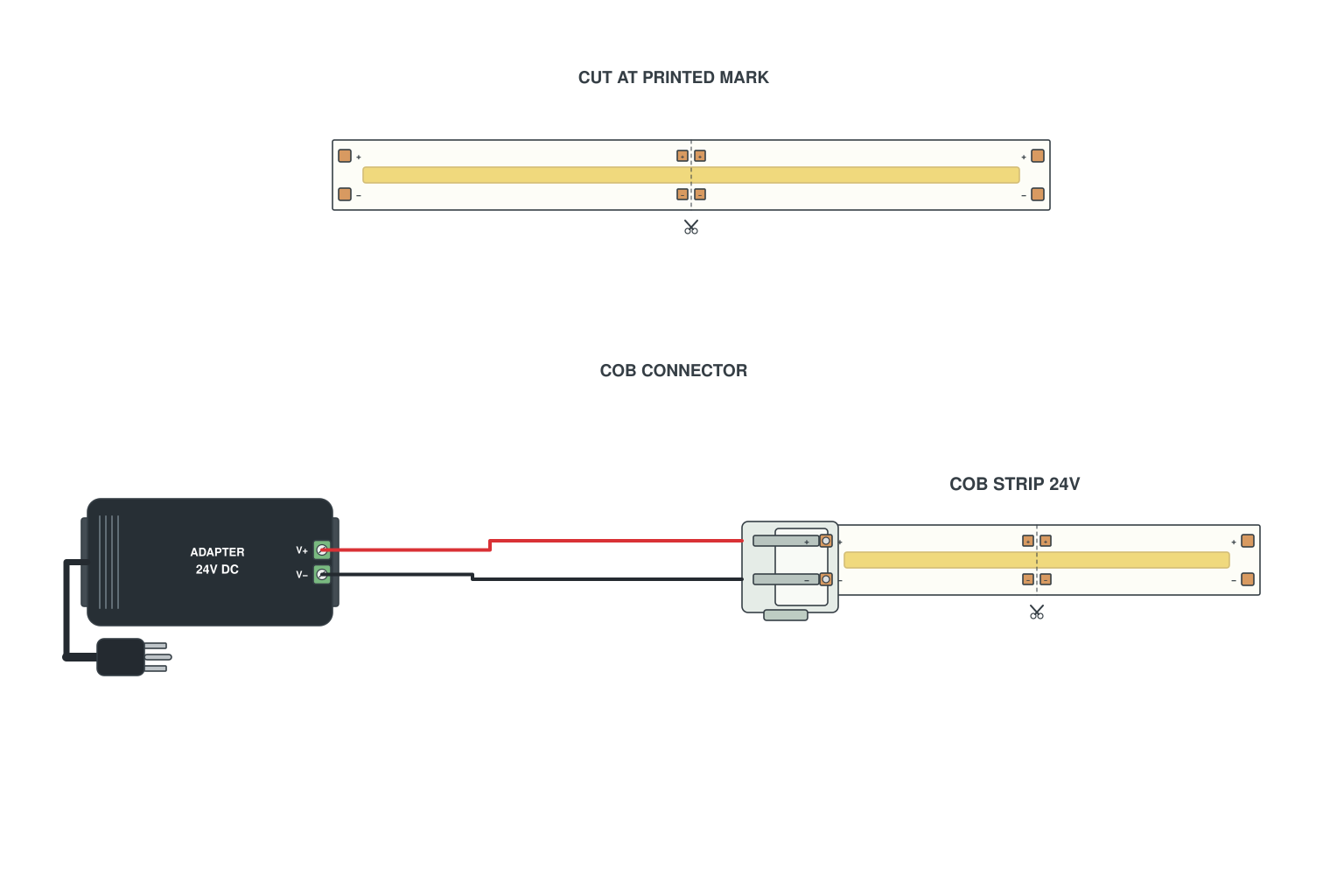
- Cut only at the printed mark (every 25-50 mm).
- Clip the COB connector onto the bare end; or tin the pads and solder wires.
- Connect to the supply or dimmer as with any single colour LED strip.
Read more: How to connect COB LED strips
LED strip layouts for real rooms
Where the power supply goes and where the feeds go in a kitchen, a cove, a staircase, a mirror and a sign. These are the layouts we draw for customers every week.
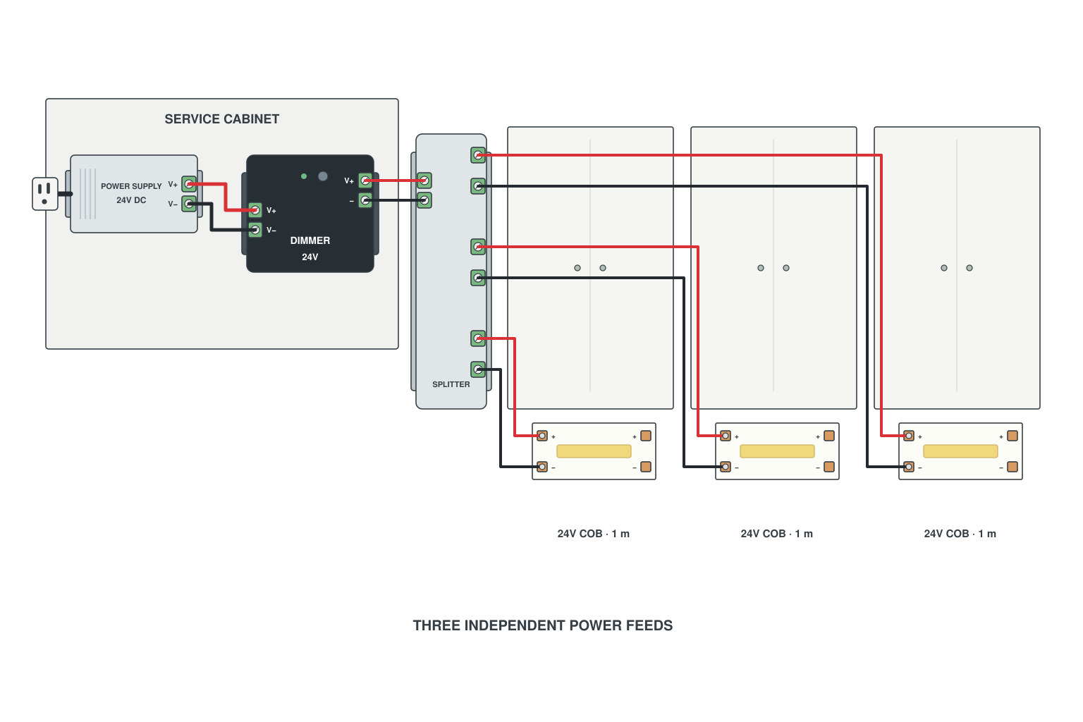
- One strip under each wall cabinet in a profile; feed wires up through the cabinet back into the corner cabinet.
- Supply and dimmer live in the corner cabinet; a splitter cable feeds each strip in parallel.
- Keep the strip 5-10 cm back from the front edge so it is not visible from the room.
Read more: How to wire single colour LED strips
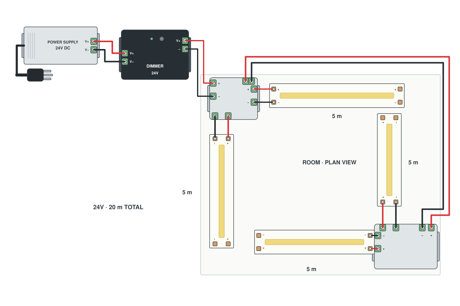
- Measure the perimeter; 4 x 5 m = 20 m is common.
- Supply in one corner; feed the two runs that start there directly, and run a feed wire along the cove to the opposite corner for the other two.
- Same strip, same voltage, one dimmer; amplifier only if the dimmer cannot carry the full current.
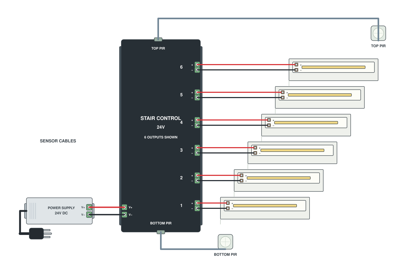
- One short strip under each tread, cut to width, plugged into the numbered outputs of the stair controller.
- PIR sensor at the top and at the bottom, on the two sensor inputs.
- Controller and its supply under the stairs or in the cupboard; set the on-time and the sweep direction.
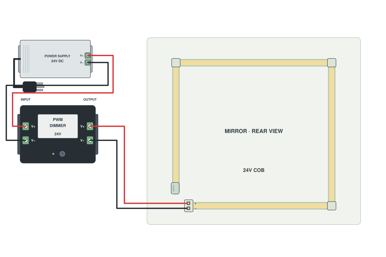
- Strip runs round the back of the mirror in a rectangle, 3-5 cm in from the edge, using L connectors at the corners.
- One feed at the bottom corner nearest the cable exit.
- Use IP65 LED strip in bathrooms; supply outside the wet zone.
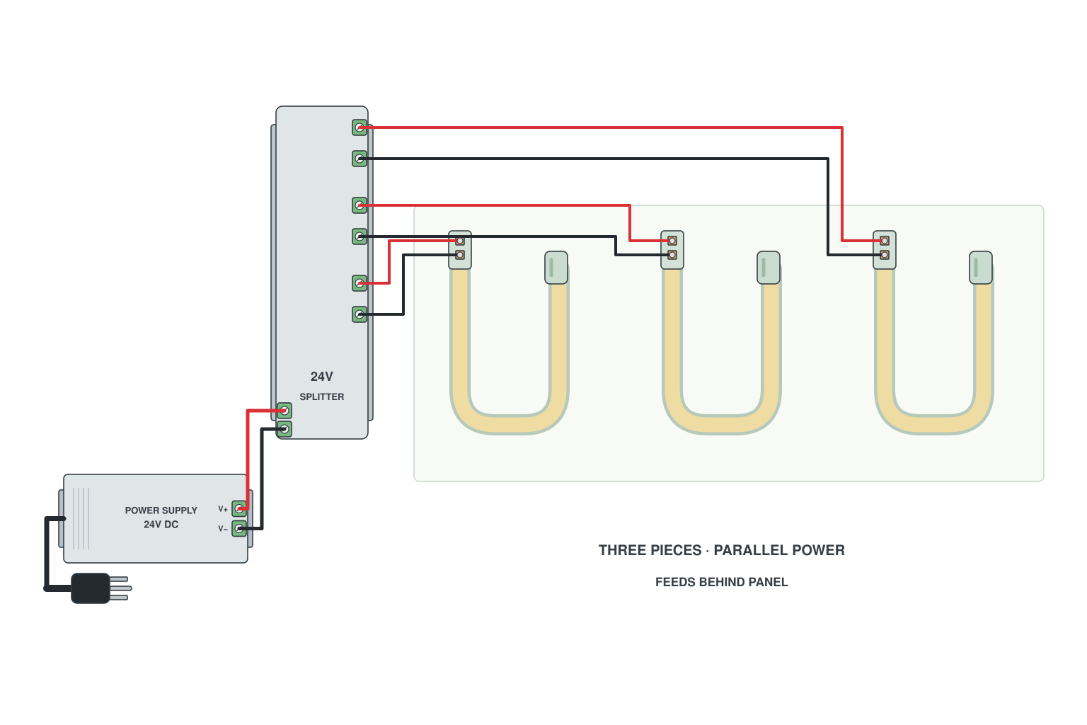
- Thread the strip into the silicone sleeve (or buy pre-made neon flex); feed wires exit at the start of each letter.
- Bring every feed to one supply behind the panel; letters are wired in parallel.
- Cap and seal the far end of each piece.
Read more: Threading strips into neon sleeves
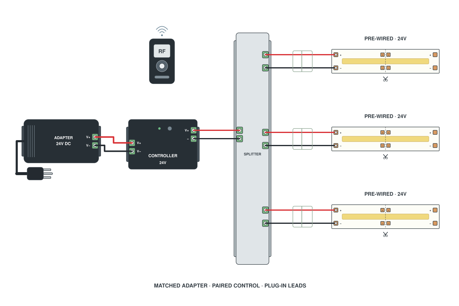
- Send us the lengths, colours and where the power point is.
- We cut the strip, solder the leads and connectors, pair the controller and pack it with the matching supply.
- On site you plug 1 into 2 into 3.
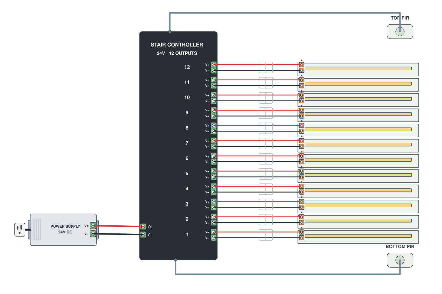
- One strip under each tread plugs into a numbered output on the controller (1 = bottom step).
- PIR sensor at the top and at the bottom on the two sensor inputs.
- Supply into the controller; set the on-time and the direction sweep.
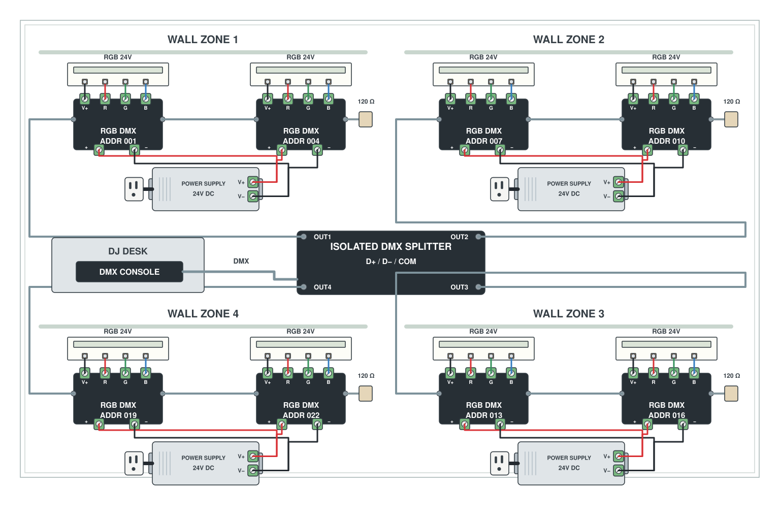
- Console at the desk; DMX cable to a splitter near the stage.
- Each splitter output feeds a group of decoders on one wall; each decoder has a strip and a local supply.
- Terminator at the end of every branch; addresses planned so nothing overlaps.
Read more: DMX control of LED strips
Three ways we wire your LED strip kit for you before it ships
Cut and soldered to length
Tell us the run lengths in the order notes. We cut at the right marks, solder leads and connectors and label each piece. Any length, no minimum.
Ultra-long, no-drop strips
10, 20, 30, 40 and 50 m constant-current and 24 V addressable rolls that need one feed point. Fewer joints, fewer supplies, nothing to inject.
Plug-and-play kits
Strip, supply, controller and connectors matched and pre-paired. Stair kits, cabinet kits and custom room kits from a sketch. See custom lighting services.
LED strip wiring not on the page? Send us a sketch
A photo of the room, the lengths and where the socket is. One of our engineers replies with the wiring plan, the parts list and a link to a filled cart, usually the same working day.
Safety: low-voltage (5-24 V DC) wiring is safe to do yourself. Anything on the mains side (110-240 V) should be done by a qualified electrician where your local rules require it.